Premature component failure, system downtime, and compromised efficiency-these are the costly results of miscalculating the forces within a pneumatic system. A primary source of this uncertainty often lies in a fundamental misunderstanding of axial load, leading to incorrectly sized actuators that are destined to underperform. The confusion between different force types can turn a meticulously engineered design into a point of operational weakness, preventing your systems from achieving their full potential.
This practical guide is engineered to deliver clarity and confidence. We will move beyond abstract theory to provide a clear, working definition of axial load, demonstrate how to calculate it accurately, and reveal why this single factor is so critical for selecting high-performance pneumatic components. You will gain the technical proficiency to distinguish between axial, radial, and eccentric forces, empowering you to select the correct actuator for any application and ensuring your systems are built for reliability and sustained success.
Key Takeaways
- Distinguish between axial and radial forces to prevent premature component wear and ensure system longevity.
- Learn the fundamental formula to accurately calculate the force generated by any pneumatic cylinder for precise design.
- Master how to use the calculated axial load to correctly size and select the optimal high-performance actuator for your application.
- Identify the risks of eccentric loads and bending moments to enhance the reliability of more complex mechanical systems.
Defining Axial Load: The Fundamentals of Force in Mechanical Systems
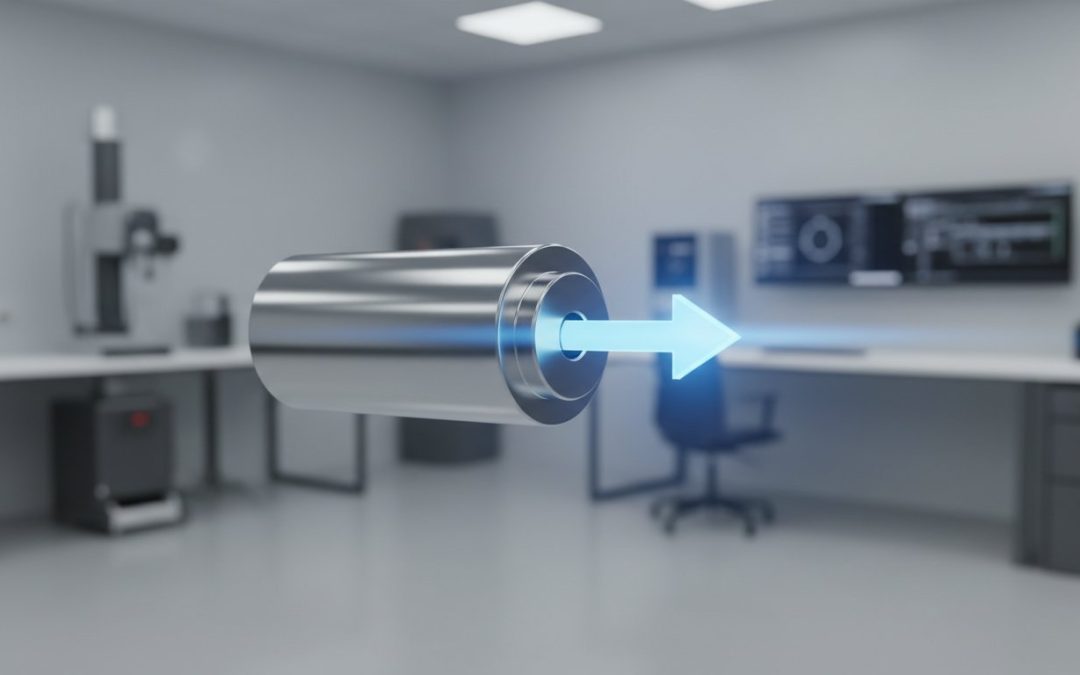
In precision engineering, understanding force is paramount. At its most fundamental level is the axial load, a force applied directly along the longitudinal, or central, axis of an object. Imagine pulling a rope in a perfectly straight line or pushing a piston directly into a cylinder-these are perfect examples of applying an axial force. This direct application of force, known as Axial loading, is the single most critical force to consider when selecting and sizing linear actuators, as it directly dictates the work the component can perform efficiently and reliably.
Tension vs. Compression: The Two Faces of Axial Load
An axial load manifests in one of two ways: tension or compression. Both are crucial for designing robust automation systems. VidoAir™ pneumatic cylinders are meticulously engineered to handle both forces with exceptional durability.
- Tensile Load (Tension): This is a pulling force that acts to stretch or elongate an object. In a pneumatic cylinder, this occurs when the rod is being pulled outward from the cylinder body.
- Compressive Load (Compression): This is a pushing force that acts to shorten or compress an object. For a cylinder, this is the force applied when the rod is extending and pushing against a workpiece.
[Diagram illustrating a cylinder rod under tension, being pulled from both ends, and another diagram showing the same rod under compression, being pushed from both ends.]
Visualizing Axial Load with Stress and Strain
For a deeper engineering perspective, we can visualize the effects of axial load through the concepts of stress and strain. When an external axial force is applied to a component like an actuator rod, it creates internal resistance within the material. This internal force per unit of area is called stress. The resulting physical deformation, or change in the object’s length, is known as strain. In essence, the axial load generates stress, which in turn causes strain, a foundational principle that governs material performance and component longevity.
Axial Load vs. Radial Load: A Critical Distinction for Component Life
In pneumatic automation, not all forces are created equal. While an actuator is designed to convert compressed air into linear motion, the direction of the opposing force is a critical factor in its performance and longevity. The primary force an actuator is built to handle is the axial load-a force applied directly along the centerline of the piston rod. Think of it as cleanly pushing a piston straight into its cylinder. However, forces can also act from the side, and this is where a crucial distinction must be made.
Most standard pneumatic actuators are meticulously engineered for high performance under axial loading conditions. They are not designed to withstand significant radial loads, which can compromise the entire system’s integrity and efficiency.
What Is a Radial Load?
A radial load, often called a side load, is a force applied perpendicular to the central axis of the piston rod. While an axial load acts along the length of the component, a radial load acts across it. Understanding the difference between an axial load and a radial load is fundamental for designing robust and reliable automation systems. These detrimental forces create bending moments on the piston rod, transferring stress to internal components not designed to handle them.
Common examples include:
- A misaligned connection between the cylinder rod and the load it is moving.
- A conveyor belt constantly pushing against the side of an extended cylinder rod.
[Diagram Illustrating Axial vs. Radial Load]
An axial load acts parallel to the piston rod’s axis, while a radial load acts perpendicularly, creating a bending force.
Why Side Loading Damages Pneumatic Cylinders
Applying a significant radial load to a standard pneumatic cylinder is a direct path to premature failure and operational inefficiency. The damage occurs because the cylinder’s internal components are not fortified to handle these lateral stresses. Proper system design is paramount to minimize or completely eliminate side loading.
The primary consequences of side loading include:
- Premature Component Wear: Radial forces cause the piston and rod to press against one side of the cylinder barrel and bushing. This leads to accelerated, uneven wear on seals and bearings, resulting in air leaks and eventual failure.
- Risk of Catastrophic Damage: Under high side loads, the piston rod can be forced to bend or, in severe cases, even snap. This causes immediate system downtime and can damage other connected components.
- Increased Friction and Inefficiency: The added pressure from side loading increases friction within the cylinder, forcing the system to consume more energy to overcome it. This leads to slower cycle times and reduced overall efficiency.
How to Calculate Axial Load for Pneumatic Cylinders
Moving from theoretical principles to practical application, calculating the force generated by a pneumatic cylinder is a fundamental step in designing any automation system. The relationship between system pressure, cylinder size, and output force is direct and predictable, allowing engineers to select components with precision. This calculation is the foundation for determining if a cylinder can handle the required axial load for a given task, whether it’s pushing, pulling, lifting, or clamping.
The Basic Formula: Force = Pressure × Area
The core of any pneumatic force calculation is the formula F = P × A. This simple equation provides the theoretical force a cylinder can generate.
- Force (F): The output force generated by the cylinder, typically measured in pounds (lbs).
- Pressure (P): The system’s air pressure supplied to the cylinder, measured in pounds per square inch (PSI).
- Area (A): The effective surface area of the piston on which the pressure acts, measured in square inches (in²). This is calculated using the formula for the area of a circle: A = πr².
It is crucial to note that the extend (push) force and retract (pull) force are different. The extend stroke utilizes the full piston area. However, during the retract stroke, the piston rod reduces the effective surface area, resulting in a lower output force. For precise engineering, the rod’s area must be subtracted from the piston area for retract calculations.
Step-by-Step Calculation Example
Consider a practical scenario where a pneumatic cylinder must lift an object weighing 500 lbs. Your compressed air system reliably provides 80 PSI.
To find the necessary cylinder size, we rearrange the formula to solve for Area: Area = Force / Pressure.
- Calculate Required Area: A = 500 lbs / 80 PSI = 6.25 in²
- Determine Piston Radius: Since A = πr², the radius is r = √(A / π). So, r = √(6.25 / 3.14159) ≈ 1.41 inches.
- Find the Bore Size: The bore size is the piston’s diameter (2 × radius), which is 2.82 inches.
Since cylinders come in standard bore sizes, you would select the next size up, such as a 3.25-inch bore cylinder, to ensure sufficient power.
Accounting for Friction and Safety Factors
Theoretical calculations provide a baseline, but real-world applications involve forces like friction from cylinder seals and component wear. To ensure reliable, long-term performance, always add a safety factor to your required axial load. A typical safety factor is 25%, meaning you would design for a force of 625 lbs (500 lbs × 1.25) in the example above.
This safety margin not only overcomes system friction but also protects the piston rod from buckling under compressive stress, a risk that increases with stroke length. For long-stroke applications, it is crucial to ensure the rod diameter is sufficient to handle the load without exceeding the critical load at which a column member will fail. This buffer ensures your actuator operates efficiently without being pushed to its absolute mechanical limits.
Need help with complex calculations or selecting the perfect high-performance cylinder for your application? Contact a VidoAir™ expert.
The Impact of Axial Load on Actuator Selection and Performance
Once you have accurately calculated the force requirements for your application, the next critical step is translating that data into the correct product selection. This is where precision engineering meets practical application. The calculated force is the primary specification used to size a pneumatic cylinder, and failure to select a component rated for the operational load can lead to decreased efficiency, premature wear, and even catastrophic system failure. Matching the cylinder’s capabilities to the application’s demands is fundamental to building a robust and reliable automation system.
Sizing Your Cylinder Bore for Optimal Force
An actuator’s output force is a direct function of its bore size and the system’s air pressure. While selecting a larger bore provides more power, it introduces critical trade-offs that impact overall system efficiency:
- Larger Footprint: Requires more physical installation space within your assembly.
- Higher Air Consumption: Increases energy usage and long-term operational costs.
The most cost-effective strategy is to select the smallest cylinder that meets your calculated force requirement, plus a recommended safety margin of 25%, ensuring robust performance without unnecessary excess.
Preventing Rod Buckling in Long-Stroke Applications
In applications with long strokes, high compressive forces can cause the piston rod to bend or bow-a failure mode known as buckling. The risk of buckling increases proportionally with the stroke length and inversely with the rod diameter. For these demanding scenarios, it is imperative to consult manufacturer-provided buckling charts. VidoAir™ also offers robust solutions with oversized rod options specifically engineered to provide the necessary stability and prevent failure in long-reach applications.
Dynamic Loads: Beyond Static Force
The forces calculated for static loads-such as holding a weight in place-are only part of the equation. Dynamic loads, generated during the acceleration and deceleration of a mass, can be significantly higher. Starting and stopping an object requires a peak force that often far exceeds the force needed to simply support it. This peak force must be factored into your total axial load calculation to ensure your selected actuator has the power to perform reliably through its entire cycle. For expert guidance on high-performance actuators designed for dynamic applications, explore the solutions at vidoair.com.
Advanced Considerations: Eccentric Loads and Bending Moments
While calculating a direct, concentric axial load is foundational, real-world applications often present more complex challenges. For engineers designing robust and reliable automation systems, understanding eccentric loads and the resulting bending moments is critical for ensuring actuator longevity and performance. An eccentric load is a force that is applied parallel to, but not directly through, the central axis of the actuator rod.
This off-center application of force creates a combination of a direct compressive or tensile force and a bending moment. The bending moment is a rotational force that attempts to bend the actuator rod, placing significantly higher stress on the rod, bearings, and seals than a purely concentric force would.
The Dangers of Eccentric Loading
Eccentric loading is a primary cause of premature actuator failure. By introducing a bending moment, it concentrates stress on one side of the piston rod and its bearing surfaces. This leads to accelerated wear on seals, galling of the rod and bearing, and in severe cases, can cause the rod to bend or fracture. Meticulously engineered systems from VidoAir™ are built to withstand demanding conditions, but proper load alignment remains a fundamental principle of sound design.
Design Strategies to Mitigate Off-Center and Side Loads
Preventing the negative effects of eccentric and side loads is achievable through intelligent system design. The goal is to isolate the actuator from these forces, allowing it to focus solely on linear motion. Key strategies include:
- Utilize External Guides: Incorporating external supports like linear rails or guide blocks is the most effective method. These components bear the side load and moment, ensuring the actuator’s force is applied purely in the axial direction.
- Select Appropriate Mounting Styles: For applications with potential misalignment, using a pivot or trunnion mount allows the actuator body to pivot slightly. This helps the actuator self-align with the load’s path of travel, reducing bending stress.
- Incorporate Stop Tubes: In long-stroke applications, the piston rod is more susceptible to buckling. A stop tube is an internal spacer that increases the distance between the piston and the rod-end bearing when fully extended, providing greater stability and support against bending.
By implementing these design considerations, you can significantly enhance the reliability and lifespan of your pneumatic systems. For complex applications requiring robust, high-performance components, explore our range of actuators and accessories designed to power your success.
From Theory to Application: Mastering Forces in Your Design
Understanding the principles of force is fundamental to robust mechanical engineering. As we’ve detailed, distinguishing between axial and radial forces, accurately calculating loads for pneumatic cylinders, and accounting for eccentric loads are all critical steps toward system longevity. A comprehensive grasp of axial load is not merely academic-it is the practical foundation for selecting actuators that deliver optimal performance, prevent premature component failure, and maximize operational efficiency.
The right knowledge demands the right components. At VidoAir™, we provide high-performance pneumatic solutions that are precision engineered for durability under the most demanding conditions. When your design requires actuators that can reliably manage force, our catalog offers the solution. Partner with us to gain the advantage of factory direct pricing for unmatched value and access to dedicated technical support from our industry experts.
Take the next step in powering your success. Browse VidoAir’s High-Performance Pneumatic Cylinders today and equip your systems with components engineered to last.
Frequently Asked Questions
What is the difference between axial force and axial stress?
Axial force is the total push or pull force acting along an actuator’s centerline, measured in units like Newtons or pounds. In contrast, axial stress is the internal pressure that force creates, calculated as the force distributed over a component’s cross-sectional area (e.g., the piston rod). While force is the external load applied, stress is the material’s internal resistance to that load. Both are critical metrics for ensuring component integrity and system longevity.
Can a standard pneumatic cylinder handle both axial and radial loads?
Standard pneumatic cylinders are meticulously engineered to manage forces along their central axis-the axial load. They are not designed to withstand significant radial (side) loads, which cause premature wear on seals, piston rod bending, and eventual component failure. For applications involving side loads, external guidance mechanisms like linear slides are essential to isolate the cylinder from these damaging forces, ensuring optimal performance and maximum service life for your automation system.
How do dynamic loads affect axial load calculations?
Dynamic loads from acceleration and deceleration introduce inertial forces that must be added to the static load of the object being moved. The total effective axial load is the sum of the static weight and this inertial force (F=ma). Neglecting these dynamic effects, particularly in high-speed automation, will lead to an undersized actuator. This results in sluggish performance, excessive component stress, and a significantly reduced operational lifespan for the pneumatic cylinder.
What happens if you exceed the maximum axial load rating of a pneumatic cylinder?
Exceeding a cylinder’s maximum axial load rating introduces extreme stress that can lead to a cascade of critical failures. This includes buckling or permanent bending of the piston rod, catastrophic failure of the rod and piston seals, and structural damage to the end caps. Operating a cylinder beyond its design limits compromises system safety, voids the manufacturer’s warranty, and will inevitably result in costly operational downtime and premature equipment replacement.
How does cylinder mounting style affect its ability to handle axial loads?
The mounting style is critical for proper force transmission and stability. Centerline mounts, such as front or rear flange mounts, are the most robust for handling high axial forces as they direct the load straight through the cylinder body to the mounting surface. In contrast, pivot mounts like a clevis or trunnion can introduce bending moments if misaligned, potentially reducing the cylinder’s effective load capacity and compromising the structural integrity of the entire assembly.
What is a ‘stop tube’ and how does it relate to axial load?
A stop tube is an internal spacer placed over the piston rod to increase the distance between the piston and the rod-end bearing when the cylinder is fully extended. This is crucial for long-stroke cylinders to prevent piston rod buckling under high compressive axial loads. By providing additional support and increasing the cylinder’s column strength, a stop tube ensures greater stability and durability, particularly in demanding, long-reach pneumatic applications where rod integrity is paramount.