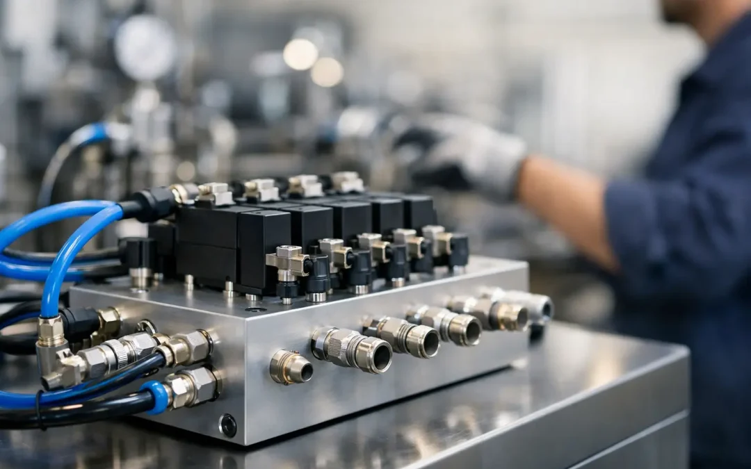
A machine that needs six valves, twelve tube runs, multiple tees, and a cabinet full of adapters has already created its next maintenance problem. Custom pneumatic manifold solutions replace that point-to-point complexity with a controlled air distribution and valve architecture built around the machine’s actual motion sequence, space claim, and service requirements. For OEMs and plant engineers, the payoff is usually more than a cleaner layout: fewer leak paths, faster response, simpler troubleshooting, and less time lost when a valve or actuator circuit needs attention.
The strongest manifold design is not simply the one that holds the most valves in the smallest space. It must deliver sufficient flow at the required pressure, isolate circuits where needed, support practical maintenance, and fit the electrical and mechanical constraints of the equipment. Getting those details right before fabrication prevents costly field modifications later.
Where Standard Valve Banks Create Problems
Standard valve banks work well when an application is straightforward and repeatable. Problems begin when the machine has mixed actuator sizes, separate pressure zones, unusual port locations, washdown exposure, or a tight enclosure. Adding fittings to force a standard assembly into the application often increases the number of threaded joints, tube bends, and potential restrictions.
Every extra connection is a possible leak source. In a high-cycle assembly cell, even a small leak can keep a compressor running longer, reduce available pressure during peak demand, and make a cylinder appear slow or inconsistent. The maintenance team may then replace a perfectly functional valve or actuator because the real issue is pressure loss upstream.
Long tube runs introduce another penalty: delayed actuator response. The volume between the valve and cylinder must fill and exhaust during every cycle. On a slow fixture, that delay may not matter. On a packaging machine, pick-and-place station, or automated inspection system, it can limit throughput and complicate motion timing.
A configured manifold can place valves closer to the actuators, consolidate supply passages, and route ports in the direction that makes sense for the machine. That does not mean every application needs a highly complex custom block. A well-selected modular manifold may be the better economic choice for low-volume equipment or systems likely to change frequently. The right answer depends on cycle rate, available space, maintenance access, expected production volume, and the cost of unplanned downtime.
Specify Custom Pneumatic Manifold Solutions From the Load Back
A reliable specification starts at the actuator, not at the manifold inlet. Define what each motion must do, then work backward through valve capacity, porting, air supply, and control requirements.
Start with motion and flow demand
Cylinder bore, stroke, operating pressure, cycle time, and load determine the air volume required for each movement. A valve with an undersized flow rating may extend and retract a cylinder during a bench test, yet fail to meet production timing once the machine runs at full speed. Restrictions from small ports, elbows, silencers, flow controls, and narrow tubing add to the total pressure drop.
For fast or high-force motion, evaluate the complete circuit rather than relying on a valve’s catalog flow number alone. Consider the distance from the valve to the cylinder, the exhaust path, and whether several actuators switch at the same time. A manifold supply passage that is adequate for one cylinder may not maintain pressure when four circuits fire together.
This is also where separate pressure zones can be valuable. A gripper may need lower, regulated pressure to protect a delicate part, while a clamp circuit needs higher pressure for holding force. A manifold configured with appropriate supply sections, regulators, or independent feeds can support both without compromising either function.
Select the valve function for failure behavior
Valve selection is a machine-safety and uptime decision, not only a port-count decision. Determine whether each actuator should extend, retract, hold position, or exhaust when electrical power is removed. A spring-return valve provides a defined default state. A double-solenoid valve can retain its last commanded position, but that behavior may be unacceptable if power loss must move the machine to a safer condition.
Also account for the actuator itself. Double-acting cylinders commonly use 5-port directional control valves, while single-acting cylinders may use 3-port functions. Vacuum ejectors, blowoff circuits, rod locks, and pilot-operated valves can require different manifold arrangements. When several functions have different failure-state requirements, a custom configuration avoids the temptation to use one valve type everywhere simply for convenience.
Design port orientation around service access
Port direction can determine whether a technician can replace a tube in minutes or remove surrounding guards and components first. Specify where supply, exhaust, work ports, electrical connectors, and diagnostic points need to face. On compact equipment, side ports may reduce height. In a crowded panel, top access may improve assembly and inspection. For mobile or heavy-equipment applications, protected routing may matter more than compactness.
Do not overlook exhaust. Restricted exhaust can slow an actuator as much as a restricted supply. Centralized exhaust ports can simplify sound control and keep contaminants away from sensitive areas, while individual exhaust treatment can be useful where circuits need separate flow control or where noise must be managed near operators.
Build for the Conditions Around the Machine
A manifold that performs well in a clean indoor automation cell may not last in food processing, outdoor equipment, refrigeration, or abrasive manufacturing. Material choice, sealing, electrical protection, and contamination control should match the operating environment.
Aluminum manifold bodies are common for their weight, machinability, and broad application fit. Stainless steel options may be warranted in corrosive, washdown, or hygiene-sensitive environments. The decision should reflect actual exposure. Specifying stainless throughout a protected control cabinet can add unnecessary cost, while using standard materials near aggressive washdown chemicals can create premature corrosion and sticking components.
Air quality matters just as much. Water, oil carryover, pipe scale, and fine debris can interfere with spool movement, clog small orifices, and shorten seal life. Proper filtration, pressure regulation, and drainage upstream protect the manifold and improve repeatability. If the application cannot tolerate lubricated air or requires a specific lubricant compatibility, identify that requirement early so seals and valves are selected accordingly.
Electrical integration deserves the same attention. Determine the available control voltage, connector style, I/O architecture, cable routing, and whether visual indication or manual override is needed. For machines with frequent setup changes, labeled valve positions and accessible overrides can reduce diagnostic time. For automated systems tied to PLC control, organized wiring and clear circuit identification prevent commissioning errors that look like pneumatic faults.
Make Troubleshooting Part of the Design
The best pneumatic assembly makes failures easier to isolate. A custom manifold should create a clear relationship between an electrical output, a valve station, a port, and a machine function. When a cylinder does not move, a technician should be able to verify supply pressure, inspect the valve indicator, use an appropriate manual override, and test the circuit without tracing anonymous tubing through an enclosure.
Consider adding gauge ports or pressure-sensing locations at meaningful points in the system. Supply pressure at the compressor does not prove that adequate pressure reaches the manifold during a high-demand cycle. A local reading can quickly distinguish an air-delivery issue from a valve, flow-control, or actuator problem.
Circuit isolation can also protect production. If one optional station or auxiliary tool develops a leak, the ability to shut off or service that branch without disabling the entire machine may justify a more advanced manifold layout. This is particularly useful in multi-station equipment where one failed circuit should not stop every station.
Labeling is not cosmetic. Permanent identifiers for valve positions, pressure zones, port functions, and electrical connections reduce reliance on tribal knowledge. For OEMs, that clarity improves field service. For plant teams, it shortens shift-to-shift handoffs and makes spare-parts planning more accurate.
When a Custom Assembly Delivers the Best Return
Custom pneumatic manifold solutions are most valuable when they remove recurring cost, not merely when they create a cleaner-looking assembly. High-volume OEM equipment benefits when a configured manifold cuts assembly labor, reduces fitting inventory, standardizes tubing lengths, and improves repeatability from build to build. End users benefit when the design reduces leak points, restores access, and shortens fault isolation during critical production runs.
There are trade-offs. A fully engineered block can require more up-front design review and may be less flexible if the machine concept changes often. A modular valve island may provide faster reconfiguration and easier expansion. The decision should be based on the machine lifecycle, not just the initial component price.
For demanding applications, provide the supplier with the circuit diagram, actuator data, required cycle times, operating pressure, environmental conditions, available space, valve functions, and electrical requirements. Those inputs turn a general valve request into a manifold configuration that is engineered for production rather than adapted at the last minute.
VidoAir supports manufacturers and automation teams with factory-direct pneumatic components and configured assemblies that keep practical serviceability in view. The useful next step is to map the current circuit’s leak points, tube lengths, pressure zones, and recurring maintenance calls. That exercise often shows exactly where a purpose-built manifold can earn its place on the machine.