Navigating the complex landscape of industrial automation presents a host of critical decisions, from deciphering the nuances between system types to selecting the precise combination of force, speed, and control for your application. The sheer number of options-stepper versus servo, ball screw versus lead screw-can make specifying the right component a formidable task. At the heart of modern, high-precision motion control is the electronic actuator, a meticulously engineered component designed to deliver unparalleled performance and efficiency when integrated correctly.
This comprehensive guide is engineered to eliminate that uncertainty. We will deconstruct the core principles of electronic actuator technology, providing the clarity you need to make confident, informed decisions for your automation systems. You will gain a robust understanding of key performance metrics, learn to differentiate between critical actuator types, and recognize the strategic advantages they offer over traditional pneumatic or hydraulic systems. Our goal is to empower you with the technical proficiency to select the optimal motion control solution that powers your success.
Key Takeaways
- Distinguish between ‘electric’ and ‘electronic’ actuators to understand how an electrical signal translates into precise physical motion.
- Match the right actuator type-such as linear or rotary-to its ideal industrial application for optimized performance and efficiency.
- Master the critical selection criteria, from load and speed to duty cycle, to confidently specify the correct electronic actuator for your automation requirements.
- Gain a clear, expert perspective on the performance trade-offs between electronic and pneumatic systems to determine the most effective technology for your specific goals.
What is an Electronic Actuator? Defining the Core Components
In the world of automation and precision engineering, the term actuator refers to a component that converts an energy source into physical motion. While a general overview of What is an Actuator? covers hydraulic, pneumatic, and electric types, it is crucial to distinguish between a simple electric actuator and a modern electronic actuator. The term ‘electric’ broadly describes any actuator powered by electricity. The key differentiator ‘electronic’ refers to the integrated control system-the onboard intelligence that enables precise, programmable control over position, speed, and force.
Unlike a simple DC motor that merely spins when powered on, an electronic actuator is a complete, self-contained system meticulously engineered for high-performance automation. It integrates three core elements: the motor, the mechanical drivetrain, and the control electronics, all working in concert to deliver reliable and repeatable motion.
The Electric Motor: The Power Source
The motor is the heart of the actuator, providing the raw power for movement. The choice of motor technology directly dictates the actuator’s performance characteristics and cost-effectiveness. Common types include:
- Brushed DC Motors: A robust and economical choice for simple, high-torque applications where precise control is not the primary objective.
- Stepper Motors: Ideal for applications requiring precise positioning and repeatability, as they move in discrete steps, allowing for accurate open-loop control.
- Servo Motors: The premium option for dynamic, high-speed applications. They utilize an encoder for continuous position feedback, enabling unparalleled precision and closed-loop control.
The Mechanical Drivetrain: Converting Power to Motion
The drivetrain translates the motor’s rotational energy into useful linear or rotary motion. This system is responsible for the actuator’s force and speed capabilities. Key components include a gearbox to manage torque and a transmission mechanism like a lead screw or ball screw. A robust ball screw offers superior efficiency and precision for high-duty cycle applications, while a lead screw provides a cost-effective and self-locking solution for moderate loads.
The Control Electronics: The ‘Brain’ of the Actuator
This is what truly defines an electronic actuator. The integrated control electronics act as the system’s brain, interpreting input signals from an external source-such as a PLC, microcontroller, or simple switch-and commanding the motor. This onboard driver often includes critical features like adjustable electronic limit switches to define the stroke, overload protection to safeguard the mechanics, and position feedback capabilities, transforming a simple motor into a smart, programmable motion device.
How Electronic Actuators Work: From Electrical Signal to Physical Motion
At its core, an electronic actuator is a meticulously engineered system designed to convert electrical energy into precise, controlled linear or rotary motion. The entire process is a seamless flow of command, conversion, and confirmation. Think of it like a central nervous system for a machine: a controller (the brain) sends a command signal (a nerve impulse) to the actuator (the muscle), which then performs a specific physical task with high accuracy.
This operational sequence is what makes electric actuation a cornerstone of modern automation, offering unparalleled control and repeatability. The process can be broken down into three critical stages:
Receiving the Command Signal
The operation begins when the actuator’s integrated or external controller receives a command signal from a primary control source. This signal dictates the desired position, speed, or force. In industrial automation, this source is often a Programmable Logic Controller (PLC), but it can also be a simple switch or a remote control in less complex applications. Common signal types include:
- Analog Signals: Such as 0-10V or 4-20mA, where the voltage or current level corresponds to a specific position.
- Pulse Width Modulation (PWM): A digital signal where the duty cycle determines the motor’s speed or position.
- Digital Communication Buses: Protocols like Modbus, CANopen, or EtherNet/IP for complex, networked control.
Motor Activation and Mechanical Conversion
Once the controller receives the command, its internal driver translates the signal into the appropriate power output for the electric motor. This electrical energy causes the motor to rotate. The true mechanical work happens next: this rotary motion is converted into linear movement through a precision gear system connected to a lead screw or ball screw. As the screw turns, it drives a nut along its length, which is attached to the actuator’s main extension rod, causing it to extend or retract with robust force.
Feedback and Position Control
Precision is the hallmark of a high-performance electronic actuator. This is achieved through a feedback loop. Sensors integrated within the actuator, such as potentiometers or encoders, constantly monitor the exact position of the rod. This real-time data is sent back to the controller. This process is central to closed-loop (servo) systems, where the controller compares the actual position to the target position and makes micro-adjustments to eliminate any error. This level of precise control is a key advantage in detailed comparisons of Electronic vs. Pneumatic Actuators. In contrast, open-loop (stepper) systems operate without feedback, executing commands based on a predetermined number of steps. For safety and equipment protection, most actuators also include end-of-stroke limit switches to automatically cut power when the rod reaches its fully extended or retracted physical limits.
Key Types of Electronic Actuators and Their Industrial Applications
The effectiveness of an automation system is directly tied to selecting the correct type of actuator. While all electronic actuators convert electrical energy into mechanical motion, they are primarily categorized by the type of motion they produce. Understanding the fundamental differences between linear, rotary, and more complex multi-axis systems is critical for specifying a component that delivers the required force, precision, and efficiency for your industrial application.
Linear Actuators: Precision in a Straight Line
As their name suggests, linear actuators excel at generating motion in a straight line. They are the go-to solution for tasks requiring reliable pushing, pulling, lifting, and positioning. Their robust construction and exceptional digital control make them a high-performance alternative to hydraulic and pneumatic cylinders, offering superior accuracy and cleaner operation.

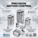
Common linear actuator form factors include rod-style (left) and rodless (right).
- Industrial Applications: Essential for assembly line automation for precise part placement, automated valve control in process industries, and operating material handling gates for sorting and diverting products.
- Key Variations: Versatile rod-style actuators provide powerful thrust, while compact rodless models are ideal for long-stroke applications in tight spaces. For intricate tasks, micro-actuators deliver precision on a smaller scale.
Rotary Actuators: Controlled Rotational Power
When an application demands precise turning, twisting, or indexing, a rotary actuator is the optimal choice. These devices provide controlled rotational motion, from a fraction of a turn to multiple rotations, with high torque and repeatable accuracy that is difficult to achieve with other technologies.

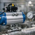
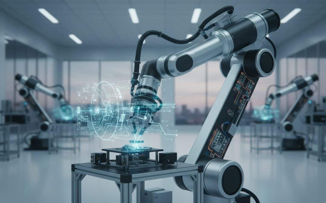
A rotary actuator providing high-torque motion for a robotic joint.
- Industrial Applications: Critical for powering robotic joints, driving indexing tables for sequential manufacturing steps, and automating quarter-turn valves in fluid or gas control systems.
- Critical Specifications: Performance is defined by torque output (the rotational force) and the available degrees of rotation, ensuring the right power and range for the task.
Specialty and Multi-Axis Systems
For the most demanding automation challenges, individual actuators are integrated into sophisticated multi-axis systems. Configurations like guided actuators, XY tables, and gantry robots combine multiple linear and rotary actuators to perform complex movements. The core of these high-performance systems is an advanced motion controller that perfectly synchronizes each axis. This integration is what enables the incredible speed and precision required in CNC machinery, robotic pick-and-place cells, and automated quality inspection equipment where multiple electronic actuators must work in perfect harmony.
Critical Selection Criteria: How to Specify the Right Electronic Actuator
Selecting the optimal electronic actuator is a process of precision engineering. The success of your automation project hinges on meticulously matching the component’s capabilities to the application’s demands. Before evaluating any specific model, the first and most critical step is to clearly define your operational requirements. This foundational work prevents costly errors and ensures high-performance, reliable motion control.
Performance Metrics: Force, Speed, and Stroke
These core parameters define the actuator’s mechanical output and often involve a trade-off; higher force typically means lower speed. Prioritizing your primary need is essential.
- Force (Load Capacity): Calculate both static (holding) and dynamic (moving) load requirements. Factoring in mass, friction, and incline prevents over-or-under-specifying.
- Speed: Define the required travel velocity (e.g., in/s or mm/s) under load to meet your process cycle time and efficiency goals.
- Stroke Length: Determine the precise distance the actuator must travel from fully retracted to fully extended to complete its task.
Operational and Environmental Factors
A robust actuator must perform reliably within its intended environment. Ignoring these factors is a common cause of premature failure and reduced service life.
- Duty Cycle: The ratio of run time to rest time (e.g., 25% means 2.5 minutes on, 7.5 minutes off). Exceeding this rating causes overheating and damage.
- IP Rating: Ingress Protection defines sealing against contaminants. An IP65 rating, for example, is suitable for washdown environments with dust and water jets.
- Operating Temperature: Ensure the actuator’s specified temperature range matches your ambient conditions, from freezing to high-heat industrial settings.
Control and Integration Requirements
Seamless integration is paramount for automation efficiency. Consider how the actuator will receive commands and report its status within your control system.
- Positional Feedback: For precise, repeatable positioning, choose an actuator with feedback sensors (potentiometer, Hall effect). For simple open/close tasks, it is not required.
- Control Interface: Match the actuator’s input (e.g., simple polarity reversal, PWM signal) with your control system, such as a PLC or switch.
- Voltage: Select a voltage (e.g., 12V DC for mobile, 24V DC for industrial automation) that aligns with your system’s power supply.
By systematically addressing these criteria, you can confidently specify an electronic actuator that delivers unmatched value and performance. For expert guidance on complex applications, the VidoAir™ team is ready to help engineer your success. Find robust solutions at vidoair.com.
Electronic vs. Pneumatic Actuators: Which Technology Powers Your Success?
Selecting the right actuator is a critical engineering decision that directly impacts system performance, efficiency, and cost. Both electric and pneumatic technologies offer distinct advantages, and the optimal choice depends entirely on the specific demands of your application. This comparison provides a clear, expert overview to help you determine which technology is the best tool for your job.
.actuator-table {
width: 100%;
border-collapse: collapse;
margin: 20px 0;
font-family: sans-serif;
}
.actuator-table th, .actuator-table td {
border: 1px solid #dddddd;
text-align: left;
padding: 8px;
}
.actuator-table thead {
background-color: #f2f2f2;
}
.actuator-table th {
font-weight: bold;
}
| Feature | Electronic Actuators | Pneumatic Actuators |
|---|---|---|
| Control & Precision | Extremely high; programmable multi-point positioning and velocity control. | Lower; typically simple end-to-end motion. Precision requires extra components. |
| Force & Speed | Moderate force and speed, often with a trade-off between the two. | Very high force-to-size ratio and extremely high cycle speeds. |
| Initial Cost | Higher, due to integrated motors, drives, and controllers. | Significantly lower component cost. |
| Operating Cost | More energy-efficient; consumes power only when moving. | Requires a continuous supply of compressed air, which can be inefficient. |
| Environmental Suitability | Sensitive to dust, moisture, and extreme temperatures without special housing. | Inherently robust and ideal for hazardous or washdown environments. |
When to Choose Electronic Actuators
An electronic actuator is the undisputed choice for applications demanding meticulous control. Their key strengths lie in high precision, complex motion profiling, and easy programmability. This makes them ideal for tasks in robotics, medical device manufacturing, and automated test fixtures where exact positioning and variable speed are non-negotiable. However, be prepared for a higher initial investment and consider if your operating environment is clean and stable enough for sensitive electronic components.
When to Choose Pneumatic Actuators
For applications demanding raw power, speed, and durability, pneumatic actuators are a robust and cost-effective solution. They deliver an unmatched force-to-size ratio and are built for high-cycle automation tasks like clamping, sorting, and pressing. Their simple design ensures reliability and a long service life, even in harsh or potentially explosive environments. While they offer less precise control than their electric counterparts, their performance and value are unparalleled for many industrial automation challenges. Explore high-performance pneumatic actuators for your system.
Powering Your Success with Precision Motion Control
As we’ve explored, electronic actuators are a cornerstone of modern industrial automation, converting electrical energy into precise, controllable motion. Understanding their core components, operational principles, and the key differences from pneumatic systems is the first step toward optimizing your machinery. The critical takeaway is that specifying the right electronic actuator is not just a technical choice-it’s a strategic decision that directly impacts your system’s performance, efficiency, and long-term reliability.
Making that strategic decision requires a partner with deep engineering expertise. At VidoAir™, we are committed to POWERING SUCCESS by helping you select the ideal motion control technology for your application. We provide dedicated technical support for system integration and offer factory-direct pricing on high-performance components. While our extensive inventory of pneumatic solutions is renowned, our core strength lies in perceptive engineering across all platforms. Contact our engineers for an expert consultation on your motion control needs.
Let’s engineer the perfect solution and move your vision forward.
Frequently Asked Questions About Electronic Actuators
What is the difference between a stepper motor and a servo motor in an actuator?
The primary distinction lies in their control systems and performance characteristics. Stepper motors operate on an open-loop system, moving in precise, incremental steps, which makes them a cost-effective solution for applications requiring reliable positioning without feedback. Servo motors utilize a closed-loop system with an encoder for continuous feedback, enabling superior precision, speed, and torque control. They are engineered for dynamic applications where accuracy and performance are paramount.
Can the speed of an electronic actuator be controlled?
Yes, the speed of an electronic actuator is precisely controllable. Velocity is managed by regulating the voltage and frequency of the electrical power supplied to the motor via a dedicated motor controller or driver. This allows for sophisticated motion profiles, including variable acceleration and deceleration. High-performance controllers enable operators to fine-tune actuator speed to meet the exact demands of the automation task, optimizing for both efficiency and cycle time.
What is the typical lifespan of an industrial electronic actuator?
The operational lifespan of a robust industrial electronic actuator is meticulously engineered for longevity and is typically measured in distance traveled or total cycles. Depending on the model, load, duty cycle, and operating environment, a high-performance unit can achieve a lifespan ranging from 25,000 to 100,000 hours of operation or millions of cycles. Adhering to manufacturer-specified load ratings and maintenance schedules is critical to maximizing the actuator’s service life and ensuring sustained performance.
How do I calculate the force needed for my application?
To calculate the required force, you must account for all factors resisting motion. This includes the mass of the load, frictional forces, and any gravitational force if the movement is on an incline. The fundamental calculation is Force = Mass × Acceleration (F=ma). It is standard engineering practice to add a safety factor of at least 25% to the calculated value to ensure the actuator has sufficient power to perform reliably under all operational conditions.
Are electronic actuators waterproof?
Waterproof capabilities in electronic actuators are determined by their Ingress Protection (IP) rating. An IP rating, such as IP65, signifies that the actuator is protected against dust and low-pressure water jets, making it suitable for washdown environments. For applications requiring submersion, a rating of IP67 or higher is necessary. It is crucial to select an actuator with an IP rating that matches the specific environmental challenges of your application to ensure durability and operational integrity.
What is the difference between a lead screw and a ball screw actuator?
The core difference is the mechanism for converting rotary motion to linear motion. Lead screw actuators utilize sliding friction between the nut and screw threads, offering a simple, cost-effective solution with excellent self-locking capabilities. Ball screw actuators use recirculating ball bearings to create rolling friction, resulting in significantly higher efficiency, speed, precision, and duty cycle capabilities. Ball screws are the premium choice for demanding, high-performance automation applications.