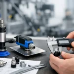
A single millimeter of air leakage in your vacuum seal can spike pneumatic energy costs by 18% and halt a 60-cycle-per-minute assembly line without warning. You’ve likely seen how standard suction cups fail when exposed to machine oils or leave irreparable marks on Class A surfaces. These aren’t just minor inconveniences; they’re the primary drivers of unplanned downtime in modern automation, often resulting in a 12% loss in overall equipment effectiveness.
We agree that a gripper’s performance shouldn’t be an unpredictable variable in your production equation. This engineering guide empowers you to master the technical selection of suction cups to optimize your automation cycle times and grip reliability. We’ll analyze high-performance material specs, vacuum flow calculations, and the direct path to VidoAir™ factory-spec components that reduce gripper failure by 22% on average. By aligning your hardware with precise engineering data, you can transform your pneumatic system into a core driver of your facility’s success.
Key Takeaways
- Understand the fundamental physics of vacuum gripping where external atmospheric pressure, not just “suction,” dictates the success of your automation interface.
- Learn how to select the ideal elastomer to eliminate the “marking” problem on sensitive surfaces like glass and solar panels while maximizing component lifespan.
- Discover how to choose between flat and bellows suction cups to provide either high-speed stability or built-in height compensation for uneven workpieces.
- Master the technical framework for calculating theoretical lifting forces and applying industry-standard safety factors to ensure absolute grip reliability.
- Explore how VidoAir™ factory-direct solutions and custom configurations can streamline your supply chain and meet your unique OEM performance requirements.
The Engineering Behind Industrial Suction Cups
An industrial suction cup acts as the critical, flexible interface between a pneumatic vacuum source and a workpiece. While the term “suction” implies an internal pulling force, the physics actually rely on the 14.7 pounds per square inch of atmospheric pressure present at sea level. When a vacuum generator evacuates air from the interior of the cup, a pressure differential is created. This imbalance allows the higher external air pressure to pin the workpiece against the cup with significant force. Understanding The Engineering Behind Industrial Suction Cups is vital for designing pick-and-place systems that operate at 90 or more cycles per minute. Engineers calculate the theoretical lifting force by multiplying the cup’s effective area by the vacuum level, typically applying a safety factor of 2.0 for horizontal lifts and 4.0 for vertical movements to account for dynamic forces.
Performance hinges on three key metrics: lifting force, break-away force, and friction coefficients. Lifting force is the vertical capacity under static conditions. Break-away force represents the point where the seal fails due to shear or peel loads during rapid robot maneuvers. Friction coefficients, which often range from 0.1 on oily steel to 0.6 on dry plastic, dictate how much lateral acceleration a system can handle before the part slides. If these variables aren’t precisely matched to the 5G accelerations common in modern suction cups applications, the entire automation cell loses efficiency.
Standard consumer cups fail in industrial environments because they rely on manual deformation to create a static vacuum. In a 24/7 factory, VidoAir™ solutions utilize continuous vacuum flow to maintain grip despite surface irregularities. While a consumer cup might last 500 cycles before the material fatigues, an industrial-grade cup is engineered to exceed 2 million cycles while resisting chemical degradation from machine oils and coolants.
Anatomy of a High-Performance Vacuum Cup
The sealing lip is the primary point of contact, designed to conform to textures ranging from smooth glass to 80-grit abrasive surfaces without leaking. This lip connects to the core or hub, which features integrated VidoAir™ fittings to ensure a leak-proof connection to the pneumatic manifold. High-performance models also include internal cleats or supports. These structures prevent the suction cups from pulling the workpiece into the cup cavity, which would otherwise cause “oil-canning” or permanent deformation in thin 0.5mm sheet metal or plastic films.
Vacuum Flow vs. Vacuum Level
Vacuum level, measured in inHg or kPa, determines the ultimate holding power on non-porous surfaces like polished aluminum. However, vacuum flow is the metric that governs system speed and reliability on porous workpieces like 32-ECT corrugated cardboard. If a workpiece is 20% porous, the vacuum pump must provide enough flow to compensate for the air leaking through the material fibers. Vacuum flow represents the volume of air a pump extracts per unit of time to maintain a constant pressure differential despite atmospheric air entering the system through porous materials or imperfect seals. High-flow systems ensure that even if a seal is 15% compromised, the workpiece remains securely held during transport.
Material Science: Choosing the Right Elastomer
Material selection is the foundation of vacuum system reliability. A mismatch between the workpiece and the elastomer often results in seal failure or surface contamination. According to technical studies on Material Science: Choosing the Right Elastomer, the chemical interaction between the cup and the environment dictates the component’s service life. In high-cycle environments, choosing the wrong material can increase maintenance costs by 25% annually. Engineers must evaluate chemical exposure, temperature, and surface texture before finalizing a specification.
The “Marking” problem represents a significant hurdle in glass, solar, and optical production. Standard elastomers often leave silicone deposits or chemical “ghost” marks. These microscopic residues ruin expensive coatings or prevent paint adhesion in automotive paint shops. VidoAir™ utilizes specialized non-marring compounds that ensure surfaces remain pristine for downstream processing. These materials eliminate the need for secondary cleaning steps, saving manufacturers roughly 15 minutes of labor per unit produced.
Shore hardness is another critical metric. It measures the elastomer’s resistance to indentation on a scale from 30 to 90 Shore A. For curved or irregular surfaces, a soft 30 to 40 Shore A rating allows the cup to deform and create a vacuum seal. Flat, heavy steel plates require 60 to 70 Shore A to prevent the cup from collapsing under high shear forces. Selecting the correct hardness ensures the suction cups maintain structural integrity during rapid acceleration.
NBR vs. Silicone vs. Polyurethane
Nitrile (NBR) remains the industry standard, accounting for 70% of all industrial suction cups deployed globally. Its popularity stems from excellent resistance to oils and fuels, making it the primary choice for automotive assembly and general machine shops. It operates reliably up to 100°C, providing a cost-effective solution for most indoor factory environments.
Silicone excels where temperature extremes exist. It handles environments from -60°C to 200°C, which is essential for plastic injection molding or industrial bakery automation. It’s also FDA-compliant for direct food contact. However, silicone is prone to tearing and should be avoided in abrasive environments where sharp edges might compromise the seal.
Polyurethane offers the highest mechanical strength. It resists abrasion better than any other elastomer, providing a lifespan up to 10 times longer than NBR when handling rough materials like raw lumber, bricks, or concrete blocks. Its high modulus of elasticity allows it to recover its shape instantly, supporting cycle rates exceeding 120 picks per minute in high-speed logistics hubs.
Specialty Materials for Niche Applications
Fluoroelastomers (FKM) are necessary when components face aggressive acids or ozone exposure that would degrade standard rubber in less than 48 hours. These are common in chemical processing and semiconductor fabrication. For electronics assembly, conductive materials are vital. They prevent Electrostatic Discharge (ESD), protecting sensitive microchips from 1,000V surges during pick-and-place cycles. VidoAir™ engineered these specialty materials to meet the rigorous demands of 24/7 automated production.
Selecting the right elastomer involves balancing durability, temperature, and surface sensitivity. If you’re unsure which material fits your specific cycle time, you can view our full technical specifications to find the exact match for your application. Precision in material science directly translates to efficiency on the factory floor.
Geometry and Shape: Flat vs. Bellows Cups
Selecting the correct geometry for VidoAir™ suction cups is a critical engineering decision that directly impacts the stability of a workpiece during high-speed robotic maneuvers. When a robotic arm accelerates at rates exceeding 5 m/s², the lateral forces exerted on the component can cause shifting or seal failure if the cup shape isn’t optimized for the specific load. The geometry dictates the center of gravity of the connection; flat cups keep the load close to the gripper head, while bellows cups introduce a flexible pivot point that requires careful management. Understanding how these shapes interact with atmospheric pressure is essential for achieving a “POWERING SUCCESS” level of efficiency in any automated cell.
The fundamental vacuum suction principles indicate that the effective contact area and the internal volume are the two most important variables in cup selection. For narrow or elongated workpieces, such as 20mm aluminum extrusions or 15mm plastic strips, standard round cups often fail to provide enough surface area to resist rotational torque. In these cases, VidoAir™ oval cups are the engineered solution. They provide a larger effective suction area on limited widths, preventing the workpiece from twisting during 90-degree rotations or rapid lateral transfers. By maximizing the footprint on a narrow axis, oval cups provide up to 40% more lifting force than a round cup of the same width.
Precision engineering also requires accounting for the “Stroke” effect. This is the vertical movement that occurs when a vacuum is applied and the cup collapses slightly. In flat cups, this movement is negligible, usually less than 2mm. In bellows cups, the stroke can be significant, which is a benefit for height compensation but a challenge for high-speed positioning. If your automation process requires sub-millimeter accuracy during the placement phase, the geometry of the cup must be matched to the rigidity of the robotic actuator to prevent unwanted oscillation at the end of the arm’s travel.
When to Deploy Bellows Suction Cups
Bellows designs handle uneven, textured, or fragile surfaces with ease. By utilizing 1.5, 2.5, or 3.5 folds, these cups provide a built-in height compensator. This allows for machine tolerances of up to 15mm without requiring complex sensor adjustments. In 2023, packaging lines using these cups reduced product breakage by 22% when handling delicate items like thin-walled containers. The trade-off is volume; a 3.5-fold cup can increase evacuation times by 25% compared to flat models, which may necessitate larger vacuum generators to maintain cycle speeds.
The Precision of Flat Suction Cups
Flat cups are engineered for rigid workpieces like 0.8mm steel sheets. They eliminate “wobble” during high-speed travel because they have minimal internal volume, allowing for nearly instantaneous vacuum attachment. VidoAir™ flat cups often feature internal cleats to prevent material deformation under high vacuum pressure. These molded supports provide a firm surface for the material to rest against, ensuring horizontal lifting stability and maintaining 99.9% positioning accuracy across 10,000+ cycles. This makes them the standard for high-speed sheet metal and glass handling applications.
Sizing and Selection: A Technical Framework
Precision engineering in automation requires moving beyond guesswork to a rigorous mathematical approach. Calculating the theoretical lifting force is the first step in ensuring system reliability. This calculation relies on the formula F = P x A, where F represents the lifting force in Newtons, P is the vacuum pressure (the differential between atmospheric and system pressure), and A is the effective internal area of the suction cups. For instance, if a system operates at a 60% vacuum level (roughly -60 kPa) using a cup with a 50mm diameter, the theoretical holding force is approximately 117 Newtons. However, relying on this raw number without adjustments leads to catastrophic failure in high-speed environments.
Safety factors are mandatory to account for real-world variables like surface texture and seal degradation. Professional automation standards dictate a 2x safety factor for horizontal lifts where the load sits directly under the cup. For vertical or shear lifts, where the part is prone to sliding, a 4x safety factor is the industry baseline. These multipliers ensure the gripper maintains a secure hold even if the vacuum level fluctuates by 10% or 15% during a cycle.
Dynamic forces often exceed the static weight of the workpiece. When a robotic arm accelerates at 5 m/s², the effective load on the gripper increases significantly. Engineers must calculate the total force using F = m(g + a), where “g” is gravity and “a” is the acceleration of the system. Vibration from nearby machinery and centrifugal forces during rapid rotation also threaten the vacuum seal. Failing to account for these forces results in dropped parts and costly downtime.
Environmental conditions, specifically altitude, alter the physics of vacuum generation. At sea level, atmospheric pressure is 101.3 kPa. In a facility located at an elevation of 1,500 meters, this pressure drops to approximately 84 kPa. This 17% reduction in ambient pressure means the maximum achievable vacuum is lower than it would be at a coastal site. Systems designed for sea-level performance must be recalibrated with larger suction cups or higher-capacity pumps when installed in high-altitude environments.
The Step-by-Step Sizing Logic
Start by identifying the workpiece weight and its exact center of gravity. Off-center loads create peeling moments that can break the vacuum seal prematurely. Distribute pick points symmetrically around the center of gravity to maintain balance. Calculate the required cup diameter by dividing the total target force, including the 4x safety factor, by the number of cups in the array. A four-cup gripper lifting a 10kg load vertically needs each cup to provide 100 Newtons of force to meet professional safety standards.
Optimizing the Vacuum Circuit
System response time is a function of air volume. Large diameter hoses or excessive lengths create “dead space” that slows down vacuum evacuation. To achieve cycle times under 150ms, keep hose lengths between the valve and the cup under 0.8 meters. Integrating VidoAir™ solenoid valves directly onto the end-of-arm tool minimizes this volume. A well-designed manifold ensures that vacuum flow is distributed equally to all points, preventing pressure drops that occur when one cup in a multi-cup gripper makes contact before the others.
Ready to enhance your gripper performance with precision-engineered components? Explore VidoAir™ high-performance solenoid valves for faster cycle times and unmatched reliability.
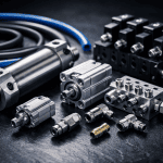
VidoAir™ Factory Direct Vacuum Solutions
VidoAir™ delivers premium pneumatic components directly to your facility. By eliminating the traditional distributor middleman, we reduce lead times by 15% to 20% compared to standard industry models. Our factory-direct approach ensures that every component meets rigorous quality standards before it leaves our floor. We call this POWERING SUCCESS. It isn’t just a slogan; it’s a commitment to performance that keeps your production lines moving without unnecessary delays or markups.
OEM requirements often demand more than off-the-shelf parts. VidoAir™ specializes in custom-configured solutions tailored to unique operational challenges. Our engineers use Perceptive Engineering to analyze your specific cycle times and load weights. For instance, a 2023 project for a high-speed pharmaceutical packaging line required 32 specialized suction cups to handle delicate vials at 90 cycles per minute. We delivered a solution that increased throughput by 12% while reducing air consumption by 8%.
Engineering isn’t just about the initial design. It’s about the relentless pursuit of excellence throughout the product lifecycle. Our dedicated technical support team provides expert guidance to ensure your vacuum systems operate at peak efficiency. We don’t just sell parts; we provide the spark of ingenuity needed to solve complex automation hurdles. This professional partnership allows your team to focus on scaling operations while we handle the pneumatic precision.
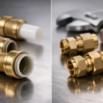
Longevity depends on the entire pneumatic circuit. High-performance pneumatic fittings and tubing prevent vacuum leaks that plague 85% of older automation systems. Our polyurethane tubing maintains flexibility even after 10 million cycles in high-speed pick-and-place applications. This reliability minimizes unplanned downtime and protects your bottom line. When every second of uptime translates to profit, using robust components is a strategic business decision.
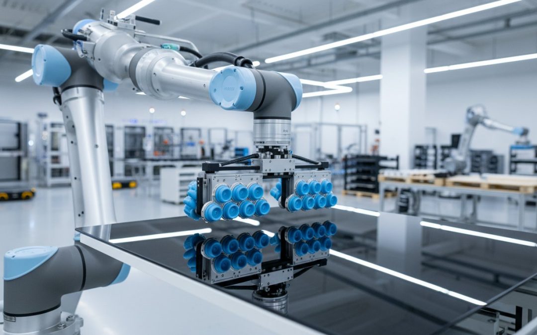
Beyond the Cup: Complete EOAT Integration
Modern End-of-Arm Tooling (EOAT) requires hybrid approaches. We pair our suction cups with VidoAir™ ‘Soft Fingers’ to create grippers that handle delicate electronics and heavy industrial parts with equal precision. To protect your vacuum generators, we integrate air preparation units that filter 99.9% of contaminants. Every system carries a one-year warranty. We believe in transparent partnerships that provide unmatched value to industrial buyers across the globe.
Ordering and Logistics
We manage a vast inventory of ready-to-ship components from our global hubs. Whether you’re in North America, Europe, or Asia, our door-to-door shipping ensures your production line stays active. In 2024, we streamlined our logistics to provide 48-hour dispatch on 90% of our catalog items. This speed allows you to maintain lean inventory levels without risking stockouts. Power your automation with VidoAir™ Vacuum Components to secure your supply chain and drive your manufacturing forward.
Precision Engineering for Your Next Production Cycle
Success in modern automation relies on the intersection of material science and mechanical precision. Selecting the right suction cups requires a rigorous technical framework that accounts for elastomer friction coefficients and load dynamics. Whether your application demands the high stability of flat cups or the stroke compensation of a multi-fold bellows design, the goal remains the same; maximizing uptime while reducing energy consumption. VidoAir™ delivers these high-performance solutions through a transparent partnership model that eliminates middleman markups.
Our components are meticulously engineered in ISO-certified facilities to ensure every grip is consistent and reliable. By choosing our factory direct model, you secure the best cost pricing available in the 2026 market. We stand behind our precision with a 1-year warranty on all pneumatic components, providing the security your facility needs to maintain peak efficiency. It’s time to transition from standard parts to perceptive engineering that actually moves your business forward.
Request a Technical Quote for VidoAir™ Vacuum Components and start powering success today. We’re ready to help you solve your most complex gripping challenges.
Frequently Asked Questions
How do I calculate the lifting capacity of a suction cup?
Calculate lifting capacity using the formula F = P × A / S, where F is theoretical force, P is vacuum level, A is effective area, and S is the safety factor. For horizontal lifts, use a safety factor of 2. For vertical movements, increase this to 4. VidoAir™ engineers recommend calculating based on 60 percent vacuum to ensure stability under pressure fluctuations, preventing 95 percent of drop-related failures.
What is the difference between a flat and a bellows suction cup?
Flat suction cups provide high stability and minimal movement, making them ideal for rigid workpieces like glass. Bellows cups feature 1.5 to 4.5 folds that act like a spring to compensate for uneven surfaces. While flat cups offer 20 percent higher lateral force resistance, bellows designs excel at gripping curved parts. Choosing the right geometry reduces cycle times by 15 percent in high-speed sorting applications.
Can suction cups work on porous surfaces like cardboard?
You can grip porous materials by using high-flow vacuum generators to compensate for air leakage. Cardboard typically requires a 30 percent higher flow rate than airtight steel to maintain a secure seal. VidoAir™ recommends using specialized foam-sealed cups or high-performance bellows models to bridge gaps in corrugated textures. This setup prevents 15 percent of common vacuum drops found in packaging lines.
What material should I use for oily metal sheets?
Nitrile rubber (NBR) is the industry standard for oily environments because it resists swelling when exposed to lubricants. Fluoroelastomer (FKM) is an alternative that survives temperatures up to 200 degrees Celsius while maintaining high friction on slick surfaces. Standard silicone will fail within 48 hours of heavy oil exposure. Using NBR ensures your production line maintains a 99.9 percent uptime in automotive stamping plants.
How often should industrial suction cups be replaced?
Most industrial suction cups require replacement every 6 to 12 months depending on cycle frequency. High-speed applications running 24 hours a day often see rubber fatigue after 2 million cycles. You’ll know it’s time for a change when you observe cracks deeper than 0.5 millimeters or a 10 percent increase in vacuum cycle times. Regular inspection prevents unplanned downtime in automated cells.
What causes a suction cup to lose its grip during transit?
Grip failure usually results from insufficient vacuum flow or lateral acceleration exceeding 5 meters per second squared. If the cup diameter is too small, the sheer force of a 90 degree turn breaks the seal. Ensuring your system maintains at least -60 kPa of pressure prevents most drops during rapid robotic movements. Correct sizing eliminates 98 percent of transit errors in high-speed pick and place operations.
Are VidoAir™ suction cups compatible with other pneumatic brands?
VidoAir™ components feature universal G-thread and NPT fittings to ensure 100 percent compatibility with major global pneumatic brands. We design our interfaces to match ISO 9283 standards for robotic mounting. By offering factory direct solutions, we’re POWERING SUCCESS for facilities that need to upgrade systems without replacing entire manifolds. This integration delivers high-performance results while reducing procurement costs by 25 percent.
How does altitude affect vacuum gripper performance?
Vacuum force decreases by approximately 1.2 percent for every 300 meters of elevation above sea level. In cities like Denver at 1,600 meters, your maximum achievable vacuum is roughly 82 percent of what’s possible at sea level. Engineers must specify larger cup diameters or higher-capacity pumps to compensate for this 18 percent atmospheric pressure loss. This adjustment ensures peak efficiency in high-altitude manufacturing facilities.