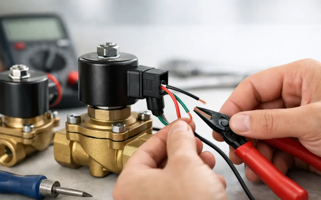
A solenoid valve that clicks but does not shift is usually not a valve problem first – it is often a wiring problem. If you are looking at how to wire solenoid valves in a production machine, air skid, or OEM assembly, the difference between a clean installation and a nuisance fault comes down to voltage verification, coil matching, and disciplined termination.
For engineers and maintenance teams, wiring a solenoid valve is rarely just about getting power from point A to point B. It affects response time, coil life, PLC output protection, troubleshooting speed, and long-term reliability in demanding applications. A valve that is electrically correct on paper can still perform poorly if the connector orientation, suppression method, or field cable selection is wrong.
How to wire solenoid valves without creating failure points
Start with the nameplate and datasheet, not the wire colors. Solenoid valves are available with AC and DC coils, different power consumption levels, connector standards, and pilot configurations. Applying 24 VDC to a 120 VAC coil, or assuming every three-pin connector is wired the same, wastes time and can damage surrounding controls.
The first check is coil voltage and frequency. Confirm whether the valve coil is 24 VDC, 12 VDC, 24 VAC, 120 VAC, or another rating. With AC coils, verify frequency if specified. Then confirm coil wattage or inrush and holding current, especially if the valve is being driven directly by a PLC output, relay card, or low-capacity transistor output.
Next, identify the connection style. In industrial pneumatic systems, you will usually see one of three arrangements: flying leads, DIN-style connectors, or terminal blocks inside an enclosure. Each can be wired correctly, but each introduces different risks. Flying leads simplify replacement in some installations but can create inconsistent field splices. DIN connectors give a cleaner serviceable connection, but only if the gasket, center screw, and internal terminals are assembled properly. Terminal block wiring is robust in panel builds, though it adds one more set of terminations that can loosen over time.
Before landing any conductor, lock out power and verify zero energy. If the valve is part of an electro-pneumatic circuit, isolate the air supply as well. A miswired coil is one issue. An unexpected actuator stroke during testing is a much bigger one.
Basic wiring sequence for a typical solenoid valve
In most cases, wiring follows a simple pattern. One side of the coil receives supply power, and the other side returns to neutral or common, depending on whether the circuit is AC or DC. If the valve includes a ground terminal, bond it properly. If it includes an LED or surge suppression module, respect polarity on DC versions.
For a 24 VDC valve, the positive supply is commonly switched through a PLC output or relay, while the negative returns to DC common. Some systems switch the negative side instead. Either approach can work, but consistency across the machine matters because it affects diagnostics and replacement work. If the connector includes polarity markings, follow them exactly. Many technicians have chased false valve failures that were really reversed polarity on a protected connector.
For AC coils, line and neutral usually feed the two coil terminals, with protective earth connected where provided. AC coils are less sensitive to polarity, but that does not mean the install is forgiving. Loose connections, undersized cable, or poor strain relief will still create heat and intermittent operation.
If a DIN connector is used, disassemble it and inspect the insert before wiring. Terminal markings are typically molded into the plastic. Tighten the conductor clamp firmly, but do not over-compress fine-strand wire without ferrules. In high-vibration equipment, ferrules and proper cable glands are worth the extra few minutes because they reduce broken strands and nuisance opens.
Pay attention to suppression devices
This is where otherwise solid installations go wrong. Solenoid coils are inductive loads. When power is removed, they generate a voltage spike. Without suppression, that spike can shorten relay life, damage transistor outputs, and create electrical noise in nearby controls.
On DC coils, a flyback diode is common. It protects the circuit, but it also makes polarity matter. Reverse the wiring and the valve may not energize, or the suppression device may fail. On AC coils, MOVs or RC snubbers are more typical. These also need to match the coil and connector design.
There is a trade-off here. Suppression improves electrical reliability, but some suppression methods can slightly affect release time. In high-speed pneumatic circuits, that delay may matter. In slower utility circuits, it usually does not. If response timing is critical, choose the suppression method with the valve dynamics and control architecture in mind.
Match the wiring method to the environment
A solenoid valve mounted on a clean machine frame inside a protected enclosure has different wiring needs than one installed near washdown zones, mobile equipment, or heat-producing machinery. Cable jacket, connector seal rating, and strain relief should match the site conditions.
Moisture ingress at the connector is one of the most common causes of erratic valve operation. So is oil contamination inside improperly sealed connectors. If the environment is wet or dirty, make sure the connector gasket is seated, the cable entry is tightened correctly, and the cable is routed to avoid direct drip paths. A good drip loop still solves real problems.
Common mistakes when wiring solenoid valves
The biggest mistake is assuming the coil and the control voltage match because the part looks familiar. Similar valve bodies often accept different coils. Always confirm the exact coil installed.
The second mistake is overloading the control output. A PLC output card may be rated for the load, but startup current, multiple simultaneous valve energizations, or shared commons can push the channel group beyond spec. If several valves are switched at once, use an interposing relay or properly rated output module where needed.
The third mistake is ignoring voltage drop. On long cable runs, especially in 24 VDC systems, the valve may see enough voltage to illuminate an LED but not enough to shift reliably under full operating conditions. This shows up as intermittent actuation, heat buildup, or chatter. Measure voltage at the coil under load, not just at the power supply.
A fourth issue is poor grounding practice. Ground is not just a compliance detail. Proper bonding helps control electrical noise and improves safety, especially where variable frequency drives, motor starters, and inductive loads share the same equipment space.
Troubleshooting a solenoid that will not actuate
If the valve does not shift, start with the electrical basics before replacing hardware. Measure actual voltage at the coil while the output is commanded on. If there is no voltage, move upstream to the connector, terminal block, output device, fuse, and supply. If there is correct voltage but no magnetic pull, check coil continuity and compare resistance to expected values if available.
If the coil energizes and pulls in but the valve still does not change state, the issue may be mechanical or pneumatic rather than electrical. Contamination, incorrect pressure differential, blocked exhaust, or a stuck pilot stage can mimic a wiring failure. That is why disciplined troubleshooting matters. Swapping parts before confirming the signal path usually turns a ten-minute fix into a half-day problem.
Heat is another clue. A coil that runs hotter than expected may be overvoltage, continuously over-energized beyond duty rating, or mounted in an ambient condition the original design did not account for. Some warmth is normal. Excessive heat, discoloration, or a burnt odor is not.
A better standard for panel builders and maintenance teams
If you wire solenoid valves regularly, standardization pays off fast. Use consistent wire numbering, standard connector orientation, documented fuse sizing, and clearly defined output grouping. Label the valve, the cable, and the PLC point so that future service does not depend on tribal knowledge.
For OEMs and integrators, the right valve package also reduces wiring errors. Preconfigured connectors, matching coil options, and application-aligned accessories can eliminate field guesswork. That is one reason many industrial buyers prefer working with suppliers that understand both the component and the system around it.
In practical terms, how to wire solenoid valves well comes down to respecting the coil as an electrical device, not just a pneumatic accessory. When voltage, protection, environment, and control architecture are all considered together, the result is faster commissioning and fewer production interruptions.
If a valve circuit keeps failing, treat the wiring as part of the design, not an afterthought. That is usually where the real fix starts.
Check Out Our Full Line of Solenoid Valves

Why Engineers Specify VidoAir™
- Dimensional consistency across product families
- High cycle life validated through real‑world testing
- Fast customization without long engineering lead times
- Application‑driven design support from pneumatic specialists
- Full system compatibility with VidoAir valves, air prep, fittings, and tubing
When you specify VidoAir™ pneumatic actuator cylinders you’re choosing components engineered to reduce downtime, simplify integration, and deliver predictable performance across millions of cycles.
We pride ourselves on delivering complete, high-quality pneumatic solutions tailored to your needs. All of our products are engineered for durability, efficiency, and ease of use, ensuring your operations run smoothly. Whether you’re upgrading an existing system or building a new one, VidoAir’s pneumatic componetns are designed to deliver top performance.
Best PracticesTo maximize the performance and lifespan of your pneumatic systems, regualr maintenance is critical. For more on maintaining pneumatic systems, visit Compressed Air Best Practices, a leading resource for compressed air system optimization.