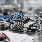
A cylinder that moves late, a valve that chatters, or a PLC output that keeps failing rarely points to one bad part. More often, the wiring scheme is the weak link. This electro pneumatic wiring guide is written for engineers, panel builders, and maintenance teams who need circuits that behave predictably under production conditions, not just on the bench.
Electro-pneumatic systems sit at the intersection of compressed air, electrical control, and machine safety. That mix creates opportunities for fast, precise motion, but it also creates failure modes that are easy to miss during design. A valve coil may be correctly rated and still overheat because of the wrong supply tolerance. A pressure switch may be wired correctly and still feed noise into an input card because cable routing was treated as an afterthought. Good wiring is not just about making a connection. It is about making the system stable under real industrial load.
What an electro pneumatic wiring guide should solve
At the design stage, the goal is simple: every electrical signal should produce the intended pneumatic action, at the right time, without stressing coils, outputs, or field devices. In practice, that means deciding how power is distributed, how outputs drive loads, how feedback devices return status, and how protection is applied across the circuit.
For most OEM and retrofit work, the core electrical devices are familiar – PLC digital outputs, relay interposing modules, solenoid valve coils, pressure switches, reed switches on cylinders, and power supplies. The mistakes happen in the interfaces between them. A 24 VDC valve bank may share supply with sensors and create nuisance drops during switching. A long cable run to a manifold may invite voltage loss that leaves the spool in an uncertain position. A mixed AC and DC control panel may work for months, then fail intermittently as transients accumulate.
That is why a practical electro pneumatic wiring guide has to focus less on textbook symbols and more on field behavior.
Start with the load, not the schematic
Before drawing a single wire number, define the electrical characteristics of each pneumatic control device. Solenoid coils are not interchangeable just because the valve function matches. Coil voltage, inrush and holding current, duty cycle, insulation class, connector style, and environmental rating all affect the wiring approach.
A single 24 VDC solenoid on a small machine can often be driven directly from a PLC transistor output if the output current rating and surge suppression strategy are correct. A bank of valves on a higher-cycle system may be better served through fused distribution and interposing relays or protected electronic outputs. The trade-off is response speed and simplicity versus output card protection and serviceability. Direct PLC control reduces parts count. Interposing relays add another failure point, but they can isolate the controller and simplify field replacement.
The same principle applies to feedback. Reed switches on cylinders are compact and common, but they can be susceptible to electrical noise and misalignment. Solid-state sensors cost more, yet often deliver cleaner, faster status signals in high-cycle automation. If the machine uptime target is aggressive, the cheaper component is not always the lower-cost decision.
Match the power architecture to the machine
Most modern electro-pneumatic assemblies use 24 VDC control power, and for good reason. It aligns well with PLC I/O, common sensors, and modular valve manifolds. But 24 VDC only performs well if distribution is handled correctly.
Separate control power by function when the application justifies it. Valve coils and inductive loads should not automatically share the same protected branch as low-level sensor circuits. When they do, switching events can create voltage dips or electrical noise that show up as false inputs, communication faults, or inconsistent sequencing. In compact equipment, a single supply may still be acceptable, but branch protection and grounding discipline become more critical.
Voltage drop deserves more attention than it usually gets. A long run to a remote manifold, undersized conductors, or too many devices on one branch can leave a 24 VDC coil seeing far less than nameplate voltage at the moment of actuation. The result may be sluggish shifting, partial spool movement, or heat buildup from repeated failed pulls. Calculate conductor sizing from actual load and cable distance, not assumption.
Wiring solenoids for reliability, not just function
A coil that energizes in testing but fails six months later usually points to protection or environment, not bad luck. Solenoid wiring should account for surges, contamination, and service access.
DC coils need suppression. That can be a diode, MOV, or dedicated protected connector, depending on response requirements and output type. A simple flyback diode is common and effective, but it slows the coil release time. On high-speed applications where valve response matters, that slower drop-out can affect cycle timing. In those cases, another suppression method may make more sense. It depends on whether the priority is output protection, switching speed, or both.
Connector selection matters too. DIN connectors with LED indication and integrated suppression simplify troubleshooting, especially on valve banks. They also reduce wiring errors during replacement. The trade-off is added component cost and a bit more physical envelope. In dirty or washdown conditions, sealing and strain relief become mandatory. An electrically perfect connection still fails if coolant, oil mist, or vibration gets into it.
Label every coil lead and every manifold position as if a technician will be replacing it at 2 a.m. because eventually one will.
PLC outputs, relays, and isolation
Output selection is one of the most consequential design choices in electro-pneumatic control. Transistor outputs are fast and ideal for DC loads, but they are less forgiving of wiring mistakes and coil surges. Relay outputs are flexible and can switch varied loads, though contact life becomes a concern in high-cycle valve control.
If the system has frequent cycling, multiple manifolds, or field wiring exposed to harsh electrical conditions, interposing relays or electronic protection modules can pay for themselves quickly. They isolate the PLC, localize failures, and make diagnostics cleaner. On a simple machine with a short duty cycle, they may be unnecessary added complexity.
A useful rule is to protect the most expensive and least convenient part to replace. In most machines, that is the PLC output card, not the relay base.
Sensor wiring is where noise shows up first
Cylinder position sensors, pressure switches, vacuum switches, and permissive devices often create the symptoms people blame on software. Inputs flicker. Steps hang. Faults appear randomly. The root cause is often poor wiring practice around low-level signals.
Route sensor cables separately from solenoid and motor power where possible. If they must cross, cross at right angles. Use shielded cable when the environment is electrically noisy, but terminate shields consistently. A shield grounded at the wrong point can become part of the problem. Keep common references stable, especially when multiple supplies or remote I/O islands are involved.
Input type also matters. Sinking and sourcing conventions must match the device and card architecture. That sounds obvious, yet many field issues start with mixed assumptions during retrofit work. The drawing may be correct for one revision of hardware and wrong for the current build. Verification at the terminal level saves hours later.
Grounding and protection are not optional details
Electro-pneumatic panels live near VFDs, motors, heaters, weld equipment, and long cable runs. That means noise, induced transients, and ground potential differences are not edge cases. They are normal operating conditions.
Protect each branch appropriately. Use individual fusing or electronic circuit protection for valve groups and sensor groups rather than one broad upstream device for everything. Localized protection makes faults easier to isolate and limits cascade failures. Bond enclosures correctly. Maintain clean 0 V reference practices. Avoid using the machine frame as a casual return path.
For safety-related functions, do not treat a de-energized solenoid as the entire safety concept unless the circuit and pneumatic behavior have been engineered for that role. Dump valves, monitored safety devices, and defined fail states belong in the design discussion from the start, not after commissioning.
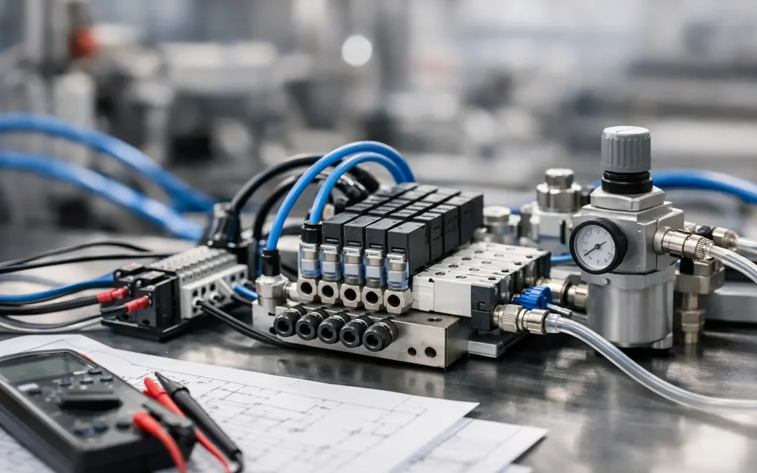
Commissioning an electro pneumatic wiring guide into the real machine
Bench validation is useful, but commissioning reveals what drawings miss. Verify actual voltage at each coil under load. Confirm current draw against expected values. Check whether suppressed coils release fast enough for the sequence timing. Test every input while nearby loads are switching.
When faults appear, resist the urge to swap parts first. Measure supply stability, observe the output device state, and inspect the return path. Many intermittent pneumatic control problems are electrical and many apparent electrical faults are caused by pneumatic load conditions that alter timing or coil heating.
This is also the point where documentation proves its worth. Terminal numbers, wire markers, coil identifiers, and manifold position callouts should all match the panel and field layout. Good documentation shortens downtime far more effectively than a drawer full of spare parts.
For manufacturers building repeat equipment, standardizing wiring practices across platforms is one of the fastest ways to reduce startup variability. Consistent connector styles, suppression methods, I/O allocation rules, and power distribution layouts make troubleshooting easier across every shipped machine. That is where a factory-direct supplier with broad pneumatic and electro-pneumatic coverage can help – not just with component availability, but with keeping the control package technically coherent.
The best electro-pneumatic wiring is rarely the most complicated. It is the design that protects the controller, gives the valve the voltage it actually needs, keeps noise out of the feedback loop, and stays readable years after the machine leaves the floor. Build for that standard, and the system will usually tell the truth when something goes wrong.