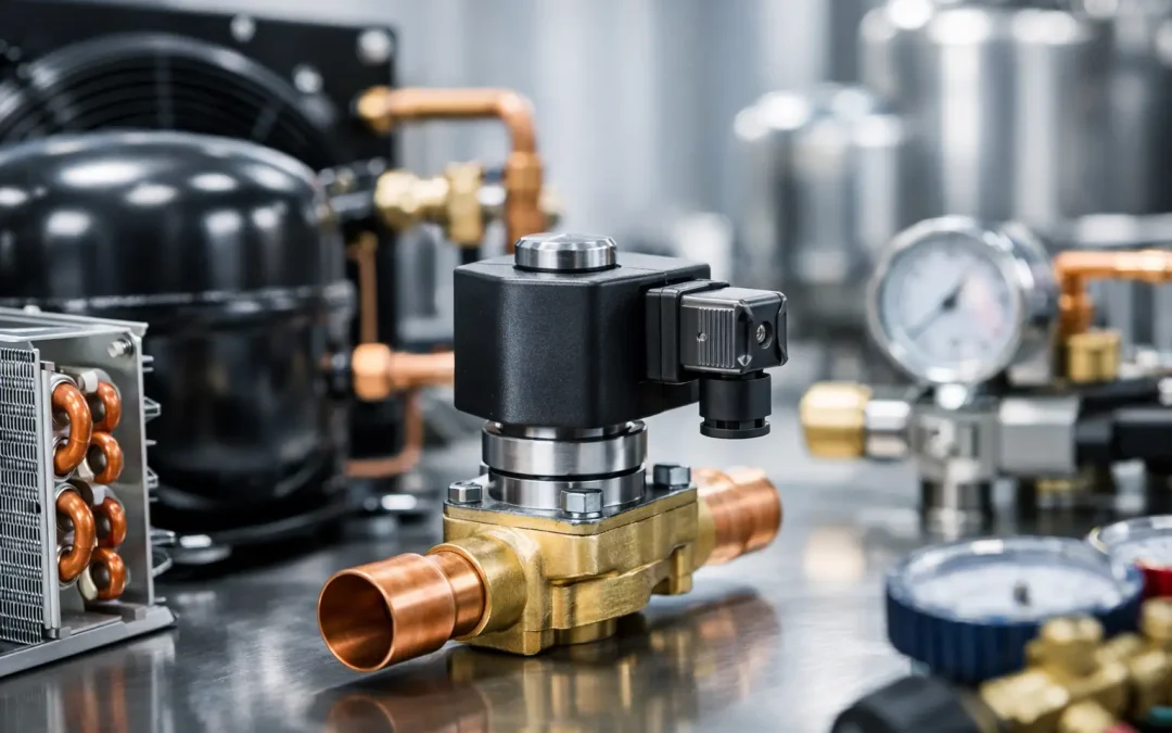
A liquid-line solenoid that will not open fully can starve an evaporator, pull suction pressure down, and send technicians looking for a restriction in the wrong place. A solenoid that fails open can flood an idle circuit during an off cycle. This refrigeration solenoid application guide focuses on the decisions that prevent those outcomes: valve function, pressure capability, coil selection, piping details, and control logic.
For OEMs, contractors, and maintenance teams, the valve is not a generic on-off device. It is a control point that has to behave predictably through pressure changes, temperature swings, compressor cycling, and long service intervals. Selection begins with the job the valve must perform, then moves to the conditions that can keep it from performing that job.
Refrigeration Solenoid Application Guide: Start With Circuit Function
The most common refrigeration solenoid application is a normally closed valve in the liquid line. When the thermostat or controller is satisfied, the valve closes and stops refrigerant flow to the evaporator. The compressor then pumps down the low side until a low-pressure control stops it. This approach reduces off-cycle refrigerant migration and helps prevent liquid refrigerant from returning to the compressor at startup.
That basic arrangement works well only when the pump-down sequence is designed as a system. The liquid-line valve must close tightly enough to allow suction pressure to fall. A leaking seat, incorrect pressure control setting, or oversized bypass path can leave the compressor running longer than intended. On the other side, a valve that closes too aggressively in a circuit with poor liquid management can contribute to pressure spikes or unstable feeding.
Normally open valves are used where flow should continue during a power loss or where the safe state requires an open path. Typical examples include certain hot-gas, defrost, oil-return, and pressure-equalization duties. They are not interchangeable with normally closed liquid-line valves simply because the port size matches. The de-energized position must support the system’s required operating and safety condition.
Hot-gas defrost deserves particular care. The valve must tolerate elevated discharge temperatures and the pressure conditions created when hot gas enters an evaporator circuit. A liquid-line valve selected only by connection size may have the wrong temperature rating, pressure rating, internal construction, or flow capacity for defrost service.
Match Valve Design to Differential Pressure
One of the most expensive selection errors is treating direct-acting and pilot-operated solenoids as equivalent. They are not.
A direct-acting valve opens by electromagnetic force acting directly on the sealing element. It can generally operate at zero or very low differential pressure, making it useful for small-capacity circuits, equalization lines, and applications where inlet and outlet pressure may be nearly the same at startup. The trade-off is limited port size and capacity relative to a pilot-operated design.
A pilot-operated valve uses system pressure differential to assist opening and closing. It is often the practical choice for larger liquid lines and higher-flow circuits, but it may require a specified minimum pressure differential to open reliably. If the system starts with equalized pressures, runs at unusually low head pressure, or includes a variable-speed compressor that changes operating conditions, a pilot-operated valve can chatter, remain closed, or open incompletely.
Check the manufacturer data for minimum opening differential pressure, maximum operating pressure differential, and rated capacity at the actual refrigerant and evaporating conditions. Do not size only from tubing diameter. A 1/2-inch line does not automatically require a 1/2-inch valve, and an oversized valve can be as problematic as an undersized one if control stability and pressure drop are ignored.
For transcritical CO2 systems, conventional valve assumptions become especially risky. High-side pressures, temperature exposure, and material compatibility require a valve specifically rated for the operating envelope. The same caution applies to newer refrigerant blends and A2L applications, where approved materials, sealing compounds, electrical protection, and local code requirements must all be verified.
Capacity Is About Conditions, Not a Single Number
Capacity tables are useful only when their rating conditions resemble the application. Refrigerant type, liquid temperature, condensing pressure, evaporating pressure, subcooling, and pressure drop all influence actual flow. A valve with adequate published capacity may still become a restriction when liquid temperature rises, available pressure drop falls, or flash gas reaches the inlet.
This is why liquid-line solenoids should normally be installed after the filter-drier and upstream of the expansion device or distributor arrangement, according to the circuit design. The valve needs clean, solid liquid refrigerant. Debris can damage the seat or obstruct pilot passages, while flash gas can reduce capacity and create noise.
Select Coils for the Real Electrical Environment
A valve body and coil are a matched assembly. The coil must match the specified voltage, current type, frequency where applicable, enclosure needs, and duty cycle. A 24 VAC coil used on a 24 VDC control circuit is not a minor substitution. It can fail to pull in correctly, overheat, or provide unreliable service.
Voltage drop is a frequent field issue on multi-valve racks and long control runs. The coil may energize on a bench but fail under load at the far end of a panel. Measure voltage at the coil terminals during pull-in, not only at the transformer or controller output. Loose terminals, undersized conductors, corroded connections, and overloaded transformers can all produce intermittent valve behavior that looks like a mechanical fault.
Ambient heat also matters. A coil mounted near discharge piping, in a crowded condensing unit, or inside a poorly ventilated enclosure operates with less thermal margin. Specify a coil with an appropriate temperature and enclosure rating, and maintain clearance for heat dissipation. Repeated coil failures are often a system-condition warning, not proof that the replacement coil was defective.
For washdown, outdoor, or corrosive facilities, assess coil enclosure protection and connector design alongside the valve body material. Stainless components may be justified in food processing, marine, or chemical exposure areas, but corrosion resistance does not eliminate the need for correct electrical sealing and cable routing.
Installation Details That Determine Reliability
Solenoids are precision control components, and poor piping practices quickly show up as leakage, noise, or sticking. Brazing heat can damage internal elastomers, seats, and pilot components if the valve is overheated. Follow the valve manufacturer’s brazing guidance, use heat control methods as required, and avoid directing flame at the coil or valve operator.
Install the valve in the approved orientation. Many refrigeration solenoids are designed to operate in any position, but others have orientation limits or perform best with the operator upright. When the valve is pilot-operated, orientation can affect internal movement and the way contaminants settle in the assembly.
Protect the valve from contamination before it ever sees refrigerant. Keep tube ends capped, purge with nitrogen while brazing, evacuate thoroughly, and replace a compromised drier. Carbon residue and scale created during installation can lodge in the valve seat or pilot orifice. A new valve that fails days after startup may be responding to installation debris, not manufacturing quality.
After commissioning, confirm operation with more than an audible click. A click only indicates that the coil created motion. Verify the pressure response across the valve, evaporator feed behavior, pump-down timing, and liquid-line temperature change. If the coil is energized but the pressure drop remains excessive, investigate a restricted inlet screen, insufficient differential pressure, damaged internal parts, or a valve sized below the actual load.
Troubleshoot by Symptom, Not by Guesswork
When a valve will not open, separate electrical causes from refrigeration causes. First confirm the controller is commanding the valve and that rated voltage reaches the coil. Then confirm coil condition, connector integrity, and correct coil specification. If electrical checks pass, evaluate pressure differential, inlet liquid quality, debris, and whether the valve design is appropriate for equalized startup conditions.
When a valve will not close, look for debris on the seat, a damaged seal, wrong flow direction, excessive temperature exposure, or a failed operator assembly. In a pump-down circuit, a slow pressure decay can also come from another leak path, such as a bypass, hot-gas valve, compressor valve leakage, or an expansion device that is not controlling properly. Isolate the circuit before condemning the solenoid.
Intermittent operation often points to voltage drop, heat, contamination, or unstable operating differential. These faults can appear only during high-load afternoons, defrost transitions, or low-ambient operation. Capturing pressures and coil voltage during the actual failure event is far more useful than testing a cooled-down system after the fact.
Build the Valve Into the System Specification
For production equipment, document the valve’s normal state, refrigerant approval, connection type, pressure and temperature ratings, coil voltage, minimum differential requirement, and intended control sequence. This gives engineering, purchasing, and field service a common reference and prevents replacement substitutions that create a hidden compatibility problem.
VidoAir supports refrigeration solenoid requirements with factory-direct component options for demanding industrial systems, including standard replacements and configured solutions where application conditions call for a closer fit. The strongest specification is not the one with the largest valve or the lowest initial price. It is the one that keeps the circuit stable, serviceable, and predictable over the equipment’s operating life.