A pneumatic circuit can look properly sized on a schematic and still miss cycle targets on the floor. The usual clue is pressure that looks acceptable at idle, then drops when a cylinder strokes, a gripper closes, or several valves shift at once. In many cases, air regulators are not the root cause by themselves, but they reveal a sizing, installation, or maintenance problem that is already costing throughput and compressed air.
For OEM builders and maintenance teams, the goal is not simply to set a lower pressure. It is to deliver stable, repeatable pressure at the point of use while preserving enough flow for the actual demand. That distinction affects actuator force, motion consistency, component life, and energy consumption.
Why Air Regulators Lose Control Under Load
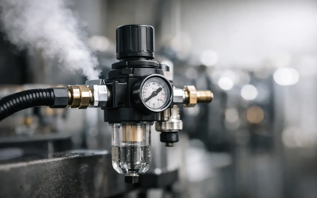
A regulator reduces upstream supply pressure and maintains a selected downstream pressure through a spring-and-diaphragm or piston-controlled mechanism. When downstream pressure falls, the regulator opens to replenish flow. When downstream pressure rises above the setting, a relieving design can vent excess air through an exhaust port.
That operating principle is simple. Real production conditions are not. A regulator may indicate 80 psi with no flow, but only supply 62 psi at a fast-moving cylinder. This difference between static and flowing performance is pressure droop. Some droop is normal, particularly as flow rises. Excessive droop points to an undersized regulator, a restricted inlet, insufficient upstream capacity, or a demand profile that exceeds the available flow coefficient.
Pressure creep is the opposite failure pattern. Downstream pressure slowly rises above the set value after the circuit stops consuming air. A worn seat, contamination on the valve sealing surface, or internal damage can allow upstream pressure to leak past the regulator. In a low-pressure clamping, gripping, or delicate handling application, creep can create inconsistent force and unnecessary risk to the workpiece.
Hunting is another common complaint. The outlet gauge oscillates, valves chatter, or a cylinder behaves inconsistently near the end of its travel. This can occur when the regulator is oversized for a very small volume, when the control mechanism is unstable at low flow, or when downstream flow changes sharply and repeatedly. Long tubing runs, restrictive fittings, and poor gauge placement can make the behavior look worse than it is.
Diagnose the Pressure Problem Before Replacing Parts
Replacing the regulator first is tempting, especially when it is easy to access. A better approach is to measure pressure at two points: immediately downstream of the regulator and as close as practical to the actuator or valve manifold experiencing the problem. Compare those readings during the highest-demand portion of the cycle, not while the machine is idle.
If pressure falls at both locations, investigate the upstream air preparation unit, filter element, supply piping, compressor capacity, and regulator flow capacity. If pressure is stable at the regulator but low at the point of use, the restriction is downstream. Undersized tubing, restrictive push-to-connect fittings, clogged silencers, poorly selected quick exhaust valves, and long manifold feeds are frequent causes.
Also verify whether the installed gauge is useful for the pressure range. A 0-160 psi gauge provides poor resolution when the critical setting is 15 psi. Gauge accuracy, mounting vibration, and a blocked gauge port can all lead technicians to adjust a regulator that is functioning correctly.
A practical diagnostic sequence includes checking the following conditions:
- Measure inlet and outlet pressure under peak flow, not only at rest.
- Inspect filter bowls and elements for water, oil carryover, and pressure loss.
- Confirm tubing inside diameter, fitting bore, and manifold port sizes match the required flow.
- Check for leaks downstream, especially at cylinder ports, valve exhausts, and damaged tubing.
- Isolate the regulator and observe whether downstream pressure creeps with demand removed.
- Review the pressure setting against the force actually required by the application.
The last point matters more than it first appears. Many systems run at 90 or 100 psi because that is the plant header pressure, not because the actuator needs it. Reducing pressure where force margin allows can cut air use and reduce impact at the end of stroke. But lowering the setting without checking peak-flow pressure can turn a stable process into an intermittent one.
Selecting Air Regulators for Actual Flow Demand
Port size is not a reliable regulator selection method. A 1/4-inch port does not automatically mean two regulators have comparable flow performance. Engineers should compare flow data, operating pressure range, pressure regulation characteristics, and manufacturer flow coefficients at conditions similar to the application.
Start with the actuator volume, cycle rate, number of simultaneous movements, and required operating pressure. A single medium-bore cylinder moving occasionally can tolerate a compact point-of-use regulator. A bank of cylinders cycling together, a vacuum generator with rapid demand changes, or an air-blow station may require a larger regulator, a dedicated branch, or local storage volume.
For high-flow applications, take the entire air path seriously. A large regulator installed behind a restrictive filter, small shutoff valve, narrow fitting, or long run of undersized tubing will not perform like the catalog flow rating suggests. The component with the lowest effective flow capacity controls the result.
Relieving vs. Non-Relieving Designs
A relieving regulator automatically vents downstream pressure when the adjustment is backed off or when pressure rises above the set point. This is often useful when operators need to lower pressure safely and quickly during setup. It also helps stabilize circuits where trapped downstream air would otherwise remain above the desired setting.
A non-relieving regulator does not intentionally vent downstream pressure. It may be preferred where exhausting air is undesirable, where the downstream circuit must retain pressure, or where released air could affect a controlled environment. The trade-off is that reducing the setting does not immediately reduce trapped downstream pressure. A separate controlled exhaust path may be required.
Standard, Precision, and Stainless Construction
Standard modular regulators fit most general factory automation systems. Precision regulators are better suited to applications that need tight control at lower pressures, such as force-sensitive clamping, small-part gripping, test fixtures, and specialty automation. Their value comes from stable adjustment and better repeatability, not from a higher maximum pressure rating.
Stainless steel air preparation devices become relevant where washdown exposure, corrosive conditions, food-related processes, chemical handling, or offshore environments challenge conventional metal finishes. Material selection should include the bowl, drain, seals, adjustment hardware, and mounting arrangement. A corrosion-resistant body cannot compensate for incompatible seals or a poorly protected gauge.
Installation Details That Protect Performance
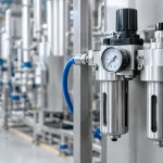
Install the regulator with flow direction matching the body marking and place it where technicians can access the adjustment and read the gauge without removing guards or reaching across moving equipment. If the machine uses a filter-regulator assembly, allow room to service the bowl and replace the element. A blocked or neglected filter can create the same symptom as an undersized regulator.
Where precise control is needed, mount a gauge close to the regulated outlet and keep the sensing path free of unnecessary restrictions. If the regulated branch supplies several loads, consider an additional gauge at the remote manifold. This makes it easier to distinguish regulator behavior from line loss during commissioning.
Protect the unit from vibration where possible. Constant vibration can loosen adjustment settings, fatigue fittings, damage gauges, and make pressure readings difficult to trust. Use proper brackets rather than allowing heavy filter-regulator-lubricator assemblies to hang from tubing alone.
Lubricated and non-lubricated circuits should also be kept intentional. Many modern pneumatic components are designed for dry, filtered air. Once oil is introduced into a circuit, downstream devices may require continued lubrication. Do not add a lubricator to solve sticking caused by contaminated air, damaged seals, poor alignment, or an incorrectly selected valve.
Maintenance That Prevents Repeat Failures
Regulator maintenance begins upstream. Drain water from filters according to the operating environment, inspect automatic drains, and replace elements before differential pressure becomes a production issue. Compressor oil carryover, pipe scale, thread sealant fragments, and rust can damage internal regulator sealing surfaces and trigger creep or erratic control.
During planned maintenance, verify that the adjustment lock functions, the gauge returns consistently, the exhaust port is clear on relieving models, and fittings show no signs of leakage or stress cracking. If a regulator will not hold a stable setting, do not compensate by repeatedly increasing the set pressure. Confirm inlet pressure, clean-air condition, downstream leakage, and actual flow demand first.
For new equipment and retrofits, specify air regulators as part of a complete air-management decision: filtration level, pressure range, flow requirement, drainage method, mounting, environmental exposure, and service access. Factory-direct component sourcing can reduce lead-time risk, but the technical configuration still has to match the machine’s duty cycle.
The best regulator setting is the lowest pressure that consistently produces the required force and cycle performance at peak demand. Establish that setting with measurements at the point of use, document it, and treat changes in pressure behavior as an early warning that the pneumatic system needs attention.