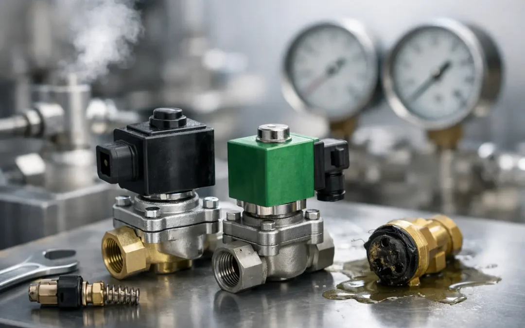
A valve that clicks but does not shift can stop an automated cell as completely as a failed PLC output. In many cases, the fault is not the electrical coil itself. Solenoid valves fail prematurely when the valve is mismatched to the media, pressure differential, duty cycle, or environment. The right corrective action starts with identifying which part of the valve function has been compromised.
For OEMs, maintenance teams, and automation integrators, selecting a solenoid valve is not simply a matter of matching port size and voltage. The valve must deliver repeatable switching under the actual conditions of the machine, including contaminated air, temperature swings, aggressive refrigerants, continuous energization, and high cycle counts. That is where specification discipline protects uptime.
Start With the Failure Pattern
A useful diagnosis separates electrical problems from pneumatic or fluid-control problems. A coil can energize correctly while the valve remains blocked, leaks internally, responds too slowly, or fails to provide enough flow to move the downstream actuator. Replacing the coil may restore operation temporarily, but it will not correct the underlying sizing or contamination issue.
When a valve will not shift, first verify the control signal at the coil terminals under load. A nominal 24 VDC coil supplied with substantially lower voltage may produce an audible click without developing enough magnetic force to move the plunger reliably. Voltage drop is common on long cable runs, undersized conductors, overloaded outputs, and poorly terminated connectors. Confirm the coil voltage, AC or DC type, and power rating against the installed component rather than relying on what is shown in a machine schematic.
If electrical supply is correct, inspect the process side. Dirt, pipe scale, degraded seals, compressor oil carryover, moisture, and thread sealant debris can prevent a plunger from seating or moving. In pneumatic systems, a clogged pilot passage can leave a pilot-operated valve stuck even though its coil is functional. In refrigeration or liquid service, debris at the seat can cause bypass leakage that looks like a failing compressor, pressure regulator, or actuator.
Direct-Acting vs. Pilot-Operated Solenoid Valves
The operating principle determines what a valve needs to work. This distinction is often missed during replacement purchasing.
A direct-acting valve uses coil force to open or close the main orifice. It can generally operate at zero differential pressure, making it a practical choice for vacuum lines, low-pressure circuits, small flow paths, and applications where pressure may be absent at startup. The trade-off is limited flow capacity as orifice size increases. Larger direct-acting designs require more coil force and may consume more power.
Pilot-operated solenoid valves use system pressure to move the main diaphragm or piston. They provide higher flow in a compact package, which makes them common in air distribution, water control, and refrigeration circuits. However, they typically require a minimum pressure differential to shift correctly. Install a pilot-operated valve where differential pressure is too low, or reverse its intended flow direction, and it may chatter, remain partially open, or fail to actuate.
Before specifying a replacement, establish whether the existing circuit has enough differential pressure across the valve in every operating state. This includes startup, shutdown, venting, and low-demand production conditions. A valve that works during full production but fails during restart may be correctly wired and still fundamentally wrong for the pressure profile.
Size for Flow, Not Just Pipe Thread
Port thread size is a connection detail, not a flow calculation. A 1/4-inch valve can have very different orifice dimensions, Cv values, and pressure-drop characteristics depending on its design. Under-sizing creates slow cylinders, incomplete clamp force, pressure starvation, and elevated energy use as operators compensate by raising supply pressure. Oversizing can also create issues, particularly when a fast, high-flow valve causes hard actuator impacts or unstable process control.
For pneumatic directional control, calculate the air demand of the actuator and required stroke time, then account for tubing length, fittings, silencers, and supply pressure loss. A valve with adequate nominal flow may still become a restriction when mounted far from a large-bore cylinder or connected through undersized tubing.
For media control, evaluate the fluid type, viscosity, temperature, inlet pressure, outlet pressure, allowable pressure drop, and required shutoff performance. Water, compressed air, vacuum, oil, refrigerant, and corrosive process media impose different requirements on body material, seal compound, internal geometry, and coil protection.
A valve selected only by connection size is an expensive shortcut. The system may run, but it is unlikely to run at its designed speed, efficiency, or cycle consistency.
Match Materials to the Actual Environment
Valve bodies and seals face more than the media flowing through them. Ambient washdown, ultraviolet exposure, vibration, heat, and airborne contaminants also affect service life. Brass is widely used for compatible air, water, and general-purpose fluids. Stainless steel is often the better choice where corrosion resistance, washdown exposure, or demanding process media are part of the application.
Seal selection deserves the same attention. NBR is a common choice for many pneumatic and oil-compatible applications. FKM offers stronger resistance to elevated temperatures and many chemicals, while EPDM is often suited to water and steam-related service but is not appropriate for petroleum oils. Refrigeration applications require components specifically rated for the refrigerant, oil, temperature range, and pressure conditions involved.
Do not assume that a valve rated for pressure is automatically suitable for every chemical or temperature. Published pressure ratings can change with media and temperature. A seal that hardens, swells, or becomes brittle can turn a normally reliable valve into a recurring leak source.
Prevent Coil Damage Before It Starts
A burned coil is usually a symptom. Overvoltage, incorrect frequency on AC coils, excessive ambient heat, restricted heat dissipation, and continuous energization beyond the coil duty rating can all shorten coil life. A normally closed valve held open for long periods may be electrically suitable only when specified with a continuous-duty coil.
Heat also raises the risk of contamination-related sticking. A dirty plunger or weak return spring may require more magnetic force to shift, increasing coil temperature and eventually causing insulation breakdown. If the same valve position repeatedly burns coils, investigate mechanical binding, supply voltage quality, enclosure temperature, and commanded on-time before installing another replacement.
Where practical, use connectors and coil enclosures matched to the environment. Wet areas, mobile equipment, dusty plants, and outdoor installations demand appropriate ingress protection and secure cable strain relief. Vibration can loosen a connector enough to create intermittent operation that appears to be a random valve failure.
Build Maintenance Into the Air and Fluid Circuit
The most effective valve maintenance often happens upstream. Compressed air should be filtered to the cleanliness level required by the valve and the rest of the pneumatic system. Water accumulation, oil carryover, and particulate contamination should be addressed at the air preparation unit, not after valves begin sticking. For critical circuits, monitor differential pressure across filters and drain condensate consistently.
Installation practices matter as well. Flush new pipework before commissioning, keep thread sealant away from flow passages, observe the valve’s flow-direction marking, and mount the valve in the manufacturer-approved orientation. Service technicians should also confirm that exhaust silencers are not clogged. A blocked silencer can slow actuator return, create backpressure, and lead teams to blame the directional valve.
For high-cycle machinery, track valve cycles alongside failure history. A valve may be operating within its published cycle-life range, yet its real service life can be reduced by poor air quality, high switching frequency, or conditions near its pressure and temperature limits. Planned replacement during scheduled downtime is less costly than waiting for a production-stopping failure.
Specify the Valve as Part of the System
High-performance solenoid valves are selected around the circuit, not pulled from a bin based on appearance. Document voltage, valve function, port configuration, normal position, media, pressure range, required flow, temperature, materials, mounting, electrical protection, and cycle expectations. This gives engineering and procurement teams a clear basis for choosing standard inventory or a configured solution.
For complex pneumatic manifolds, refrigerated processes, or equipment exposed to severe conditions, technical review before installation can avoid repeated field modifications. VidoAir supports industrial buyers with factory-direct components and configuration guidance where standard valves do not fully match the application.
The most reliable valve is rarely the one with the lowest purchase price. It is the one that shifts cleanly at the required speed, seals under real operating pressure, withstands the environment, and can be replaced without delaying production.