A slide table that lands accurately during a dry-cycle test can still miss position after several hours of production. The usual cause is not a mysterious actuator defect. Precision motion control components perform as a system, and the actuator, guide, valve, air supply, payload, tubing, sensors, and mounting structure all contribute to the final result.
For engineers and maintenance teams, the practical question is not whether an individual component meets its catalog specification. It is whether the complete axis can repeatedly place, clamp, transfer, or index a real load at the required rate without creating a maintenance burden. That distinction is where many motion problems begin – and where a better specification process pays off.
Start With the Motion Requirement, Not the Bore Size
Cylinder bore is often the first number selected because it is easy to calculate force from pressure and piston area. Force matters, but it is only one part of a precision motion application. A cylinder with adequate theoretical force can still produce inconsistent end position, side loading, bounce, or slow cycle recovery.
Define the motion in operational terms: load mass, center of gravity, stroke, cycle rate, orientation, external process force, required stopping behavior, and acceptable positional variation. Include the worst case, not only nominal conditions. A horizontal transfer may be simple at room temperature with a clean fixture, then become unpredictable when tooling accumulates residue or a downstream station introduces contact force.
For guided pneumatic motion, calculate force with a realistic pressure allowance and account for friction, seal breakaway force, and pressure loss across valves and fittings. Avoid sizing so close to the minimum that normal supply variation changes the result. Extra force margin is useful, but excessive oversizing also creates harder impacts, higher air consumption, and greater demand on cushioning or external shock absorbers.
Where Precision Motion Control Components Lose Accuracy
Pneumatic systems are excellent for fast, durable point-to-point motion. They are less forgiving when the application treats them like a rigid mechanical axis. Compressed air is compressible, seals create friction, and payload dynamics change through the stroke. Those realities do not prevent repeatable performance, but they must be addressed in the design.
Side Load and Moment Load
A standard rod cylinder is designed primarily to generate linear force. When a load is mounted far from the rod centerline, the load creates a moment that can accelerate bearing wear, cause rod deflection, and make the carriage bind. This is a frequent source of “inconsistent cylinder” complaints.
Use a guided cylinder, slide table actuator, or external linear guide when the load has offset weight, overhang, or process contact forces. Review the allowable moment ratings in the intended mounting orientation. A design that looks acceptable statically may fail under rapid acceleration and deceleration because inertia multiplies the applied load.
The mounting surface matters as much as the actuator. A thin bracket or unsupported machine frame can flex enough to consume the tolerance budget. Precision engineering at the component level cannot compensate for a structure that moves every time the axis stops.
End-of-Stroke Impact and Bounce
Internal cushions reduce metal-to-metal impact, but they are not a universal precision solution. Cushion adjustment changes with load, speed, supply pressure, and temperature. When a heavy payload must stop consistently at high speed, external shock absorbers or a dedicated mechanical stop may be the better choice.
A mechanical datum can establish final position, while the pneumatic actuator supplies the force to reach and hold that datum. This arrangement is common in clamping, pallet location, and assembly fixtures. It separates repeatable positioning from the variable behavior of pneumatic deceleration.
Do not compensate for impact by closing a flow control until the cylinder barely moves. Excessive restriction can cause sluggish cycling, pressure imbalance, and stick-slip behavior. Meter-out flow control is commonly effective for pneumatic cylinders because it creates back pressure that stabilizes motion, but the best arrangement depends on load direction and the application’s safety requirements.
Air Quality and Pressure Stability
Contaminated or unstable air turns a well-selected actuator into a variable. Water, oil carryover, particulate, and degraded tubing can affect seals, valves, and flow paths. Pressure drops caused by undersized regulators, long small-diameter runs, or simultaneous demand from nearby equipment reduce available cylinder force at the exact moment a machine needs it.
Install air preparation sized for the actual flow demand, place it where it protects the circuit, and establish a drain and filter service routine. For washdown, corrosive environments, or clean process areas, stainless steel air preparation devices and compatible materials may be necessary. Material selection should follow the environment, not simply the lowest initial component cost.
Build the Axis Around Controlled Flow
Valve and tubing choices are often treated as commodity decisions. In high-cycle automation, they directly influence response time, speed consistency, and energy use. A large actuator fed through a small valve or restrictive fitting will not achieve its expected performance. Conversely, an oversized valve can make a lightly loaded axis difficult to control.
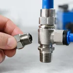
Match valve flow capacity to cylinder volume, desired cycle time, line length, and required speed. Keep plumbing runs short where response time matters. Tubing internal diameter, bend radius, push-to-connect fitting geometry, and exhaust treatment all create restrictions. If two nominally identical stations cycle differently, compare the complete pneumatic path before replacing actuators.
Quick exhaust valves can improve speed in some applications by releasing air close to the cylinder. They are not always the right answer. Faster exhaust can increase impact energy and noise, particularly on vertical or high-inertia loads. The target is controlled motion that meets cycle time, not maximum speed at every cost.
For repeatable sequencing, use sensors that suit the environment and controller logic that recognizes real machine states. Cylinder-mounted magnetic switches are effective for end-position confirmation, but they do not prove that a part is seated, a clamp reached force, or a slide is free of obstruction. Add process sensors when the consequence of a false completed signal is a damaged tool, rejected part, or safety event.
Choose the Right Motion Architecture
Some applications need pneumatic precision, while others need servo-level position control. The boundary depends on required tolerance, load behavior, cost, cycle rate, and process risk.
Pneumatic guided actuators are often the efficient choice for two-position handling, clamping, singulation, pressing against a hard stop, and short-stroke transfer. They offer high force density, simple control, and durable operation in demanding industrial environments. Specialty actuators and slide table designs can package guidance, compact mounting, and load handling into a smaller footprint than a separate cylinder-and-guide assembly.
Electric motion may be justified when the axis must stop at multiple programmable positions, maintain a changing position under load, follow a controlled velocity profile, or provide detailed position feedback. That does not make electric hardware automatically superior. It adds controls complexity, commissioning requirements, and different maintenance considerations.
A hybrid design is frequently the practical answer. Use pneumatic actuators for fast clamp, lift, eject, or transfer functions, then reserve servo axes for variable-position operations where their additional cost delivers measurable process value. This approach keeps a machine efficient without forcing a single technology onto every motion task.
Troubleshoot Repeatability Before Replacing Parts
When an axis begins missing position, maintenance teams often replace the cylinder first. A more disciplined check can prevent repeated failures and unnecessary downtime. Verify supply pressure at the valve during motion, then compare extend and retract times under the actual load. Inspect tubing for kinks, crushed sections, and loose fittings. Check for contamination in filters, abnormal exhaust restriction, and cushion adjustments that have drifted.
Next, isolate the mechanical side. With air removed and safety procedures followed, inspect the load path for loose mounts, worn guides, bent rods, tool interference, and fixture movement. Look for changes that occurred after a tooling revision or collision. A cylinder may be performing normally while an external guide or bracket is creating the apparent motion fault.
Finally, confirm sensor placement and PLC timing. A sensor that is mounted at the edge of its switching range may flicker with vibration. A controller that starts the next sequence step immediately after a position signal may not allow time for the load to settle. Small timing adjustments can help, but they should not hide a mechanical impact or pressure problem.
VidoAir supports these decisions with factory-direct pneumatic components, configured solutions, and technical guidance for applications where standard catalog selection does not fully address the load, environment, or cycle requirement.
The most reliable motion systems are specified with tolerance budget in mind: reserve structural stiffness for the load, control air quality and flow, use guidance where moments exist, and establish a positive datum when final position truly matters. That approach turns a collection of parts into an axis that keeps producing when the line is under pressure.