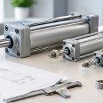
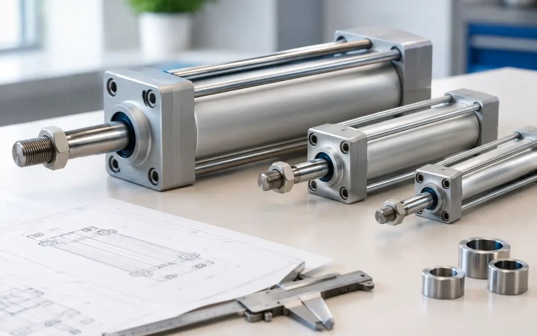
A cylinder that moves the load on a clean bench can still stall on the production floor. Pressure drop through fittings, side loading, seal breakaway, and a worn guide system can consume the margin that looked adequate in a simple force calculation. This pneumatic cylinder bore sizing guide is built for that reality: selecting enough actuator force for repeatable motion without oversizing the air system, valve, and machine structure around it.
Start With the Actual Force Requirement
Bore selection begins with the highest force the cylinder must produce at any point in its cycle, not simply the weight of the part. For a horizontal pusher, that may be friction, cutting resistance, material variation, or a jam-clearing condition. For a vertical axis, it includes the moving mass, gravity, guide friction, acceleration, and any process force.
The theoretical extension force is:
Force = Pressure × Piston Area
Piston area is calculated as:
Area = π × bore² ÷ 4
Use pressure in psi and area in square inches to obtain force in pounds-force. A 2-inch bore has an area of approximately 3.14 square inches. At 80 psi, its theoretical extension force is about 251 lbf.
That number is not the usable machine force. It assumes full regulated pressure reaches the cylinder port and that every pound of pressure converts into motion. Real pneumatic systems do not behave that cleanly, especially during high-speed cycling.
Apply a Practical Sizing Margin
For typical industrial automation, a cylinder should generally be sized with a force margin of 25% to 50% above the calculated running load. A clean, guided transfer application with stable supply pressure may operate well near the lower end. A press, clamp, ejector, package handling station, or application with variable friction should have more reserve.
The required margin depends on what happens when conditions change. If a cylinder only indexes an empty fixture, a modest margin can be appropriate. If it must overcome sticky product, contamination, misalignment, or intermittent high breakaway force, undersizing turns into nuisance stoppages and inconsistent cycle times.
Do not solve every uncertainty by selecting the largest available bore. A larger cylinder consumes more compressed air per stroke, can hit the end of travel harder, and may require a higher-flow valve, larger tubing, and more substantial mounting. The right target is controlled excess force, not maximum force.
Calculate Extension and Retraction Separately
A double-acting cylinder does not produce the same force in both directions. On extension, air acts on the full piston area. On retraction, the rod occupies part of that area, reducing the effective surface available for pressure.
Retraction force is calculated as:
Retraction Force = Pressure × (Piston Area – Rod Area)
This difference matters when the return stroke performs useful work, such as pulling a fixture, retracting a loaded slide, stripping a part from a tool, or lifting a mechanism through linkage geometry. It also matters on compact cylinders, where rod diameter may take up a meaningful percentage of piston area.
Specify the force requirement for each direction separately. A cylinder selected only from extension force can be adequate on the forward stroke and marginal on retraction. If retraction is the critical motion, calculate it first and confirm the extension force does not create an excessive impact or clamping load.
Use Available Pressure, Not Compressor Pressure
A regulator set to 90 psi does not guarantee 90 psi at the cylinder during motion. The pressure available at the actuator can fall because of undersized air preparation units, restrictive solenoid valves, small fittings, long tubing runs, quick exhaust devices, or multiple cylinders cycling at once.
For bore sizing, use the minimum pressure expected at the cylinder under peak flow. In a well-designed system, this may be close to the regulated setpoint. In a long-run installation with small tubing and fast-moving actuators, the difference can be large enough to change the bore requirement.
Pressure loss is often misdiagnosed as a weak cylinder. If an actuator performs properly at low speed but slows or stalls when cycle speed increases, inspect the supply path before increasing bore size. A larger bore may make the problem worse by demanding even more air flow.
A practical example
Assume a vertical pick-and-place axis requires 180 lbf to lift the payload, tooling, and moving carriage under worst-case conditions. Adding a 35% margin brings the force target to 243 lbf. If the cylinder receives a true 80 psi at the port, a 2-inch bore produces roughly 251 lbf on extension and is technically sufficient.
That selection has little room for supply variation. If dynamic pressure can drop to 70 psi, the same bore produces about 220 lbf, below the target. Moving to a 2.5-inch bore produces about 344 lbf at 70 psi, giving useful reserve. The valve, tubing, cushioning, and guide system must then be verified for the increased flow and force.
Account for Friction, Side Load, and Misalignment
Pneumatic cylinders are designed to generate linear force. They are not intended to carry significant side load, absorb cantilevered loads, or compensate for poorly aligned tooling. A larger bore can conceal those problems briefly, but it does not correct them.
Rod seal friction, bearing friction, and breakaway friction all reduce usable output. External guides may add further resistance, particularly if rail alignment changes under load. In applications using a rodless cylinder, slide table actuator, or guided actuator, the manufacturer’s load and moment limits are just as important as force capacity.
If the load is offset from the rod centerline, use external linear guides or a guided cylinder arrangement. If the process creates a turning moment, verify allowable pitch, yaw, and roll moments through the full stroke. This is often the difference between a cylinder that lasts for millions of cycles and one that develops rod wear, seal damage, and inconsistent positioning.
Consider Stroke Length and Rod Buckling
Bore size alone does not determine whether a cylinder can push a load safely. Long strokes increase the risk of rod buckling when the rod is in compression. A cylinder can have plenty of theoretical force yet still be limited by rod diameter, mounting style, and the unsupported length of the rod.
Buckling risk rises with long strokes, high thrust, poor alignment, and fixed mounting conditions that place the rod under compression. For long-stroke pushing applications, review the manufacturer’s rod buckling data and consider a larger rod option, guided mechanism, or a different actuator configuration. Do not assume a larger piston bore automatically improves push capability on a long, slender rod.
Mounting also changes the result. A rigidly mounted cylinder with a properly supported load behaves differently from a pivot-mounted cylinder driving a linkage. Linkage geometry can reduce available force dramatically near an unfavorable angle, so calculate the mechanical advantage at the weakest point of travel.
Match the Bore to Valve Flow and Cycle Speed
Bore sizing and valve sizing are connected. A larger bore has more volume to fill and exhaust. If valve flow is limited, the cylinder may have sufficient static force but fail to achieve the required speed. This is particularly common in high-cycle packaging, sorting, and assembly equipment.
Confirm cylinder volume, stroke time, tubing length, fitting restrictions, and required speed before finalizing the control package. A high-flow solenoid and correctly sized tubing can often improve performance more effectively than raising pressure or changing bore. Exhaust-side flow control should be used to manage speed and cushioning, while supply restrictions should be minimized where rapid response is required.
End-of-stroke energy also increases as bore size and speed increase. Adjustable pneumatic cushioning can reduce impact, but it is not a substitute for proper deceleration on high-inertia loads. External shock absorbers, mechanical stops, or controlled motion profiles may be necessary for demanding applications.
Pneumatic Cylinder Bore Sizing Guide: A Field Checklist
Before releasing a cylinder specification, confirm four items: the worst-case force in both directions, minimum dynamic pressure at the ports, load guidance and moment limits, and required flow for the target cycle time. Then check stroke length, rod buckling, mounting geometry, temperature, contamination exposure, and any special requirements for corrosion resistance or washdown service.
For applications with changing products or tooling, specify the expected range rather than the nominal condition. A configured-to-order actuator may be the better engineering choice when standard bore, rod, mounting, or sensing options create compromises elsewhere in the machine.
A correctly sized pneumatic cylinder should not merely complete a demonstration cycle. It should maintain controlled, repeatable motion after pressure fluctuations, normal wear, and real production variation begin. That is the standard worth designing for.