
A production line that still runs on an aging PLC may look stable right up to the moment a failed processor, discontinued I/O card, or unavailable programming cable turns a minor fault into days of lost output. This PLC migration project example follows a practical packaging-cell upgrade where the objective was not simply to replace a controller. The objective was to protect uptime, preserve proven machine behavior, and create a control platform maintenance could support for years.
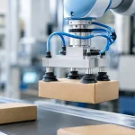
The cell indexed formed trays through a pneumatic slide, loaded product with a vacuum pick device, verified position with cylinder switches, and discharged finished packs through a conveyor. The existing PLC was functional but obsolete, with limited diagnostic capability and no practical path for remote support. Its replacement had to fit into a tightly scheduled weekend shutdown.
PLC Migration Project Example: Defining the Real Scope
The original request sounded simple: replace the processor and keep the machine running. The engineering review showed why that wording can be dangerous. A PLC migration changes the point where electrical inputs, outputs, operator commands, safety signals, pneumatic devices, drives, and production data meet. If the team treats it as a like-for-like hardware swap, hidden dependencies surface during commissioning.
The project team started with a physical and functional audit. They documented every input and output at the terminal level, then compared that list against electrical drawings, the existing program, and machine operation. Several discrepancies appeared immediately. Two spare outputs had been repurposed for stack-light functions, one photoeye was wired normally closed despite the drawing showing normally open, and a valve bank had an undocumented manual override procedure used during jam recovery.
That audit also separated the equipment into three categories: production controls, machine safety, and operator information. Safety circuits were not moved casually into standard PLC logic. The safety function was reviewed against the machine’s current risk assessment and validated independently after installation. A new PLC does not automatically make an old safety design acceptable.
Before selecting hardware, the team established measurable acceptance criteria. The upgraded cell had to maintain its existing cycle time, recover predictably after an air-pressure interruption, retain the same safe stop behavior, and provide clear fault messages for the most common stoppages. Those criteria gave maintenance, operations, and the integrator a shared definition of success.
Build the I/O Map Before Writing New Logic
The most valuable document in this project was the I/O cross-reference. Each legacy address was mapped to a new physical terminal, tag name, signal description, device location, normal state, voltage type, and test method. A tag called `Input_14` was replaced with a useful name such as `Tray_Extended_PE`, while the original address remained in the migration notes for troubleshooting.
This step uncovered a common issue in pneumatic machinery: a single output does not always represent a single action. One solenoid output energized a directional valve for cylinder extension, but the PLC considered the motion complete only after a reed switch confirmed the cylinder had reached position. The program also monitored a vacuum switch before permitting product transfer. Migrating outputs without preserving those permissives can produce motion that looks correct during a dry test and fails under production conditions.
The I/O map should capture at least these four details for every critical device:
- The electrical signal type and normal operating state
- The physical device, terminal, and panel location
- The process condition that permits the signal to change
- The expected machine response if the signal is missing, delayed, or stuck
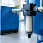
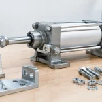
For pneumatic outputs, the team recorded valve coil voltage, connector style, valve function, actuator bore and stroke, available plant pressure, and the related feedback device. This made it possible to identify two weak points before startup: one worn cylinder sensor and one undersized air preparation assembly that allowed pressure to sag during simultaneous cylinder movement.
Design for Cutover, Not Just for Operation
A migration is often constrained by the production calendar. In this case, the line could be down from Friday evening through Sunday afternoon. That window was too short for open-ended panel work, so the new control enclosure was built and checked off-line.
The new enclosure used labeled terminal blocks, segregated control and power wiring, documented spare I/O capacity, and included a managed network connection for future diagnostics. The project did not replace every field wire solely because it was old. That would have expanded risk and outage duration. Instead, technicians replaced damaged conductors, relabeled questionable cable runs, and megger-tested circuits where appropriate.
Pre-commissioning also included a tabletop review of every operating mode: automatic production, manual jog, setup, jam recovery, fault reset, emergency stop, and restart after power loss. These modes are where copied logic often fails. A machine can run one cycle in automatic and still have an unsafe or frustrating recovery sequence.
The programming approach retained the proven sequence of operations but reorganized the code into readable routines for conveyor control, pneumatic motion, vacuum handling, alarms, and human-machine interface functions. The team avoided a blind conversion of legacy addresses into new software. Old programs frequently contain forced bits, bypasses, and abandoned branches that nobody has touched for years. Rebuilding the logic around documented machine states took more engineering time, but it reduced long-term maintenance risk.
Commissioning the Control System in Layers
During the shutdown, technicians installed the panel, landed field wiring, and performed point-to-point checks before enabling machine motion. Each input was verified at the PLC and on the operator display. Each output was tested with the actuator isolated where possible. Solenoid coils were confirmed for correct valve response, and feedback sensors were checked at both ends of every cylinder stroke.
The sequence then moved through controlled layers. First, the team tested utilities: 24 VDC power stability, air supply pressure, vacuum generation, and network communication. Next came individual devices, followed by manual machine functions. Only after those checks passed did the team run automatic cycles without product, then with product at reduced speed, and finally at normal production rate.
This staged method matters because a pneumatic fault can resemble a programming fault. For example, the tray slide initially failed to extend consistently during the dry-cycle test. The output energized correctly, the valve shifted, and the PLC waited for the extended sensor. The actual issue was a restrictive fitting at the cylinder port combined with lower-than-expected pressure at the regulator. Replacing the fitting and correcting the air-prep setting restored the intended motion time. Changing PLC timers would have hidden the mechanical issue rather than solved it.
For demanding pneumatic control sections, component quality and configuration deserve the same attention as the PLC. VidoAir supports engineers with configured pneumatic components, solenoids, air preparation equipment, fittings, tubing, and vacuum hardware that can help standardize replacement parts during a controls upgrade.
What Changed After Startup
The upgraded cell met its original cycle-time target, but the larger gain came from fault visibility. Instead of a generic machine stop, the operator interface now identified whether the fault involved low air pressure, a missing tray, a vacuum confirmation failure, an unmade cylinder sensor, or a conveyor drive issue. Maintenance could diagnose a stop at the machine instead of tracing unlabeled wires against outdated prints.
The migration also introduced trade-offs. More detailed diagnostics required additional engineering and a cleaner tag structure. Newer hardware created a learning curve for technicians accustomed to the legacy platform. And retaining the existing field devices reduced downtime, but it meant some aging sensors and valves remained on a planned replacement list. That was the right decision for this outage, not necessarily for every machine.
A complete migration package included updated electrical drawings, I/O lists, program backups, operator instructions, spare-parts recommendations, test records, and a list of remaining risks. The team also documented final regulator settings and cylinder timing under normal load. Those details are easy to overlook, yet they prevent the next technician from treating a commissioning adjustment as a mystery.
The best next step after a successful cutover is to use the new diagnostics while the machine is healthy. Trend air pressure, record normal actuator cycle times, and correct small deviations before they become the next unplanned migration project.