A vacuum cup that releases a part halfway through a robot transfer rarely fails without warning. More often, the system has been losing margin for weeks through small leaks, poor cup contact, restricted flow, or a vacuum source sized only for ideal conditions. Effective vacuum loss prevention protects more than pick reliability. It protects cycle time, product quality, operator safety, and the production schedule.
For automation engineers and maintenance teams, the goal is not simply to reach a target vacuum level during an empty-cup test. The goal is to maintain enough holding force at the point of use when real parts vary, surfaces change, filters load, and multiple stations cycle at once. That requires treating vacuum as a complete circuit rather than a single component.
Why Vacuum Margin Disappears on Working Machines
A vacuum system can appear healthy during commissioning and still become unreliable in production. The reason is that vacuum performance depends on both vacuum level and available flow. Vacuum level provides holding force; flow allows the system to evacuate volume quickly and overcome leakage. A system that reaches a high vacuum reading eventually may still be too slow or too sensitive to support a fast pick-and-place cycle.
Leaks are the usual starting point, but they are not the only cause. Porous corrugated material, textured molded parts, warped panels, dusty surfaces, damaged lips, undersized tubing, and restrictive fittings all reduce usable performance. In multi-cup tooling, a single uncovered cup can consume enough flow to collapse vacuum across the entire circuit unless each branch is controlled.
This distinction matters when troubleshooting. If vacuum drops immediately when a part is picked, inspect cup sealing, part porosity, and leakage paths. If vacuum builds slowly even with a good seal, look for inadequate ejector capacity, excessive line volume, blocked filters, or undersized supply plumbing. If vacuum loss occurs only when adjacent machines operate, investigate compressed-air pressure and flow capacity upstream of the vacuum generator.
Vacuum Loss Prevention Starts at the Point of Contact
The suction cup and the workpiece determine whether the rest of the design has a realistic chance of success. A high-capacity vacuum generator cannot compensate indefinitely for a cup that is poorly matched to the part.
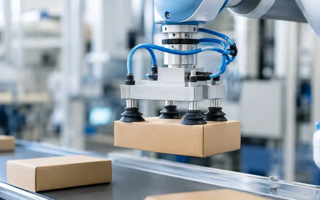
Cup selection should account for material, surface finish, temperature, geometry, lateral forces, and expected variation. A soft, flexible cup may seal well on a slightly irregular surface but can deform under side loading. A firmer cup may position parts more consistently but can struggle with uneven or textured surfaces. Bellows cups are useful where height compensation is required, while flat cups are often better for stable, smooth workpieces.
Holding force should also include a safety factor that reflects the actual motion profile. Vertical lifting, rapid acceleration, robot wrist rotation, and oily surfaces all increase the required margin. A part that can be held statically at a given vacuum level may still shift or release during a high-speed move. If a tool regularly runs near its minimum holding-force requirement, the correct solution is usually more effective gripping area, improved cup geometry, or a revised vacuum circuit – not simply a higher setpoint.
For parts with holes, cutouts, or inconsistent placement, use tooling that minimizes exposure of unused cups. Mechanical zoning, spring-loaded cup modules, and individual shutoff devices prevent one poor contact point from draining the entire manifold.
Control Leakage at Each Vacuum Branch
Check valves and vacuum-saving valves are among the most practical devices for preserving grip in multi-cup systems. A check valve helps retain vacuum in a branch when supply conditions fluctuate. A vacuum-saving valve closes or limits flow through a cup branch that is not covered by a workpiece. The best choice depends on the application.
A simple check valve is useful when a brief supply interruption must not immediately release the load. A vacuum-saving valve is more effective when tools encounter variable part sizes or intentionally use multiple cups with only some engaged on each cycle. Neither device replaces proper cup selection, but both can prevent localized leakage from becoming a machine-level failure.
Size the Vacuum Circuit for Real Cycle Conditions
Vacuum generators are often selected by maximum vacuum rating alone. That is incomplete. An ejector or electric vacuum pump must be sized for evacuation time, system volume, expected leakage, duty cycle, and compressed-air availability.
Start with the required response time. Determine how quickly the cups, tubing, manifold, and any vacuum reservoir must reach the minimum gripping vacuum after contact. Long tubing runs and oversized manifold cavities add volume that must be evacuated on every pick. Reducing unnecessary internal volume can improve response without increasing air consumption.
Then account for leakage under normal operating conditions. A tightly sealed machined plate requires little sustaining flow after evacuation. A porous carton or textured automotive trim panel may require substantial continuous flow to maintain vacuum. These applications benefit from generators with adequate flow capacity and controls that prevent open branches from wasting air.
Compressed-air supply quality is equally important with pneumatic ejectors. An ejector rated at a specified supply pressure will not deliver its catalog performance if pressure drops at the machine during peak demand. Verify pressure at the generator inlet while the system is operating, not at the plant header during idle conditions. A restricted filter, undersized regulator, long feed line, or shared air demand can create a pressure drop that looks like a vacuum fault.
Use tubing and fittings sized for both evacuation speed and physical durability. Small tubing may simplify routing but creates restriction, especially on longer runs. Sharp bends, crushed tubing, and fittings with narrow internal passages add losses that are easy to overlook. Place the vacuum source close to the tooling when fast response is critical, or use a properly sized reservoir near the end effector when the application needs short-term reserve capacity.
Build Detection Into the Machine Logic
A reliable system should detect vacuum loss before a released part becomes a downstream problem. Vacuum switches and pressure sensors provide the feedback needed to confirm pick, verify hold, and trigger a controlled fault response.
Set a pick-confirmation threshold that reflects the minimum vacuum required to safely move the part, not the highest vacuum achievable under perfect conditions. If the threshold is too high, normal material variation can create nuisance faults. If it is too low, the machine may move a part with insufficient holding force. Many applications benefit from two thresholds: one to confirm a successful pick and another lower threshold to identify a developing loss during transfer.
Machine logic should also use timing intelligently. If vacuum does not reach the pick threshold within the expected time, the problem may be a missed part, a damaged cup, or a supply issue. Stopping the sequence before motion begins prevents dropped product and avoids collisions caused by an empty end effector.
For high-value or hazardous handling, consider redundancy. Dual vacuum circuits, separate cup zones, or mechanical retention can be justified when a release could damage equipment or injure personnel. The trade-off is added cost and controls complexity, so redundancy should be applied where risk and downtime exposure support it.
A Practical Troubleshooting Sequence
When a stable system begins losing vacuum, avoid replacing components at random. Test from the workpiece backward. First, inspect cup lips for cuts, hardening, contamination, and permanent deformation. Then isolate the tooling branches to identify whether one cup or zone is consuming excessive flow.
Next, measure vacuum directly near the cups and compare it with the reading at the generator. A large difference points to restriction, excessive hose length, or a leak in the line. Check filters, silencers, fittings, manifolds, and valve seals. Finally, verify compressed-air pressure and flow at the ejector under the same operating demand that produces the fault.
This method separates a gripping problem from a generation problem. It also gives maintenance teams data they can use to decide whether a replacement cup, a revised manifold, a larger generator, or improved air preparation is the right corrective action.
Design for Service, Not Just Startup
The most dependable vacuum systems make wear visible and replacement straightforward. Locate filters where technicians can access them. Use gauges or sensors at meaningful diagnostic points. Standardize cup types where possible, but do not force one cup material across applications with different temperature, surface, or cleanliness requirements.
Preventive maintenance intervals should be based on actual conditions rather than a calendar alone. Dusty processes, abrasive materials, oil mist, and high-cycle equipment accelerate cup and filter wear. Trending evacuation time and vacuum level can reveal degradation before production sees a failed pick.
VidoAir supports industrial vacuum circuits with components selected for demanding automation environments, from vacuum generators and cups to fittings, tubing, valves, and air preparation hardware. The strongest result comes from matching those components as a working system, with enough capacity and diagnostic feedback to handle the variation that real production always introduces.
A vacuum circuit with measurable margin will not eliminate every handling challenge, but it gives your team time to respond before a small leak becomes a lost shift.