A hiss near a machine is easy to dismiss when production is moving. Across a plant, however, small losses at fittings, valve manifolds, tubing runs, and cylinder connections force compressors to run longer, reduce available pressure, and make cycle performance less predictable. Effective pneumatic leak detection turns those scattered losses into documented maintenance work with a measurable operating impact.
For experienced maintenance teams, the objective is not simply to find every audible leak. It is to identify air losses that affect energy consumption, machine availability, product quality, or the capacity of the compressed-air system. That requires a repeatable inspection process, the right detection method for the environment, and repairs that address the reason a leak developed in the first place.
Why pneumatic leaks create production problems
Compressed air is one of the most expensive utilities in a manufacturing facility. Leakage increases compressor duty cycle even when production demand is unchanged. If the system cannot maintain pressure during peak demand, operators may compensate by raising the compressor setpoint. That response often increases energy use while masking undersized distribution piping, poor air preparation, or unresolved leakage.
The production cost can be more immediate than the utility cost. A leaking fitting downstream of a regulator can destabilize pressure at a gripper, slide table, or actuator. A cylinder may still extend, but with slower motion, weaker clamping force, or inconsistent end-of-stroke timing. In automated equipment, those marginal conditions become intermittent faults that take far longer to diagnose than a clearly failed component.
Leaks also introduce a maintenance burden. A compressor running harder generates more heat and moisture, increasing the load on dryers, filters, drains, and air preparation units. In dusty or washdown environments, degraded seals and damaged tubing can turn a minor air loss into a recurring reliability issue.
The best pneumatic leak detection method depends on the job
No single method is ideal for every machine. A practical program combines methods based on the leak location, ambient noise, accessibility, and the level of documentation required.
Ultrasonic inspection for operating equipment
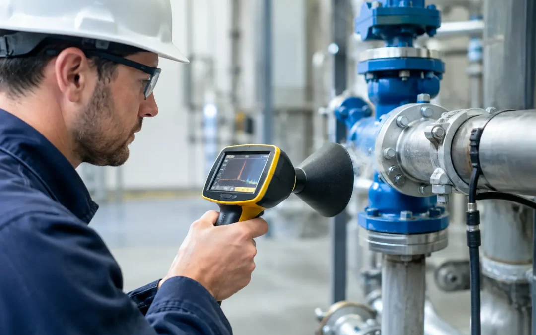
Ultrasonic detectors are the preferred tool for most production-floor inspections. Pressurized air escaping through a small opening creates high-frequency turbulence, often above the range of human hearing. The detector converts that signal into an audible tone or visual reading, allowing technicians to find leaks in noisy areas without shutting down the system.
This approach is especially effective around valve islands, threaded fittings, push-to-connect connections, quick exhaust valves, regulators, and long overhead distribution lines. Use the detector at a consistent sensitivity setting where possible, then move closer to confirm the source. Nearby leaks can create misleading readings, so isolate the suspected point by shielding it, briefly actuating the local circuit, or closing a branch valve when the process permits.
Ultrasound finds the source efficiently, but the reading alone is not always a direct measure of air volume. Distance, surface reflections, and background ultrasonic sources can affect it. Use detector data to rank and locate defects, then quantify system impact with flow or pressure testing when repair priorities need stronger justification.
Soap solution for exact confirmation
A compatible leak-detection fluid remains a dependable confirmation tool for accessible connections. Apply it to a suspected fitting, threaded joint, tube interface, cylinder port, or manifold gasket. Growing bubbles identify the point of escape.
This method is inexpensive and highly specific, but it has limits. It is impractical for large systems, overhead piping, hot surfaces, dirty equipment, and components that cannot be wetted. It should also be used carefully around electrical enclosures and sensitive process equipment. After verification, remove residue if the fluid manufacturer recommends it.
Pressure-decay and flow testing for isolated circuits
When a leak is internal, intermittent, or difficult to hear, isolate the circuit and measure pressure decay over time. This method is valuable for cylinder circuits, fixture clamps, vacuum generators, and equipment acceptance testing. A controlled pressure drop can indicate leakage even when the actual point is inside a valve, cylinder, or inaccessible assembly.
For larger systems, a flow meter installed at a machine inlet or branch line provides a clearer picture. Measure consumption during normal production, then compare it with consumption during an approved idle condition. The difference can expose off-shift air demand and show whether completed repairs are producing a meaningful reduction.
Pressure-decay testing requires discipline. Temperature changes, regulator creep, trapped volume, and intended exhaust paths can distort results. Stabilize the circuit before testing, record starting pressure and test duration, and make sure all expected loads are in their normal safe state.
A field workflow that produces useful repair priorities
Leak surveys fail when they produce a long list of tags with no consistent ranking. A stronger workflow gives maintenance and operations a common basis for action.
Start by reviewing compressor run time, system pressure trends, and production complaints. A sudden rise in unloaded compressor operation may point to a distribution leak. A recurring low-pressure alarm at one machine may indicate a local restriction, a leaking branch, or both. This context helps separate high-value work from cosmetic findings.
During the walkdown, inspect components that see vibration, motion, heat, chemicals, or repeated disconnection. These include tubing near moving axes, fittings at cylinder ports, regulator bowls, drain assemblies, valve manifold gaskets, quick-connect couplings, and flexible connections at machine interfaces. Listen for changes during machine motion. Some leaks only appear when a cylinder rod reaches a certain position or when a valve shifts under load.
Record the asset, exact location, component type, operating pressure, detector reading or test result, and a photo if your maintenance system supports it. Then classify the repair based on safety exposure, production impact, estimated air loss, and access requirements. A small leak on a noncritical branch may wait for planned maintenance. A leak affecting a safety clamp, robotic end effector, or high-cycle packaging station should be addressed sooner.
After repair, retest at the same pressure and operating condition. Verification matters because a fitting can appear corrected while the actual source is a cracked tube, damaged thread seal, worn spool seal, or internal actuator seal.
Find the cause, not just the escaping air
Many recurring pneumatic leaks come from installation practices rather than defective components. Tubing cut at an angle, scored tubing outside diameter, insufficient insertion depth, and side loading on push-to-connect fittings are common causes. Tubing should be cut squarely with a proper cutter, inserted fully, and routed with enough support and bend radius to prevent repeated stress at the connection.
Threaded joints need the correct sealing method for the fitting style and media. Excess thread sealant can migrate into valves and restrict flow, while inadequate sealing leaves a leak path. Do not overtighten fittings to stop a leak. Over-torque can damage threads, distort sealing surfaces, or crack ports, particularly on compact valves and air-preparation assemblies.
Internal leakage deserves separate attention. A valve may leak from supply to exhaust because of contamination, worn seals, or spool damage. A cylinder may bypass internally across the piston seal, producing drift or reduced holding capability without an obvious external hiss. In those cases, replace or rebuild the affected component based on the equipment design, available service kits, and the consequences of failure.
Poor air quality shortens seal life. Water, compressor oil carryover, abrasive particles, and incompatible lubricants can damage valves and actuators long before a leak becomes visible. Properly selected filters, regulators, dryers, and drains protect the entire circuit, not just the component nearest the compressor room.
Design leak resistance into new equipment
OEMs and integrators can reduce future leak exposure during design. Minimize unnecessary joints, use tubing and fittings rated for the actual pressure and environment, and provide access to valves, regulators, and diagnostic ports. A component hidden behind guarding may be technically serviceable but costly to inspect or replace.
Specify components for the motion profile rather than selecting solely by port size. High-cycle actuators, aggressive slide table motion, and mobile equipment vibration create different demands on seals, mounts, and tubing retention. Stainless steel air-preparation devices and corrosion-resistant fittings may carry a higher initial cost in washdown or outdoor service, but they can reduce repeat maintenance where standard materials degrade quickly.
At VidoAir, factory-direct pneumatic components, air preparation hardware, fittings, tubing, valves, and actuators can be configured around the pressure, media, environmental exposure, and cycle requirements of the application. The most effective replacement is not merely the part that fits the port. It is the component that restores performance without repeating the failure mode.
Turn leak detection into a maintenance control
A quarterly leak survey is useful, but high-demand operations often benefit from a more targeted cadence. Inspect critical cells after major maintenance, after line relocations, when compressor run time shifts, and whenever operators report sluggish or inconsistent pneumatic motion. Keep a baseline for each high-use machine so changes are visible before they become production interruptions.
Pneumatic leak detection delivers its strongest return when it is treated as a control for air consumption and machine reliability, not a one-time hunt for hissing fittings. Document the loss, repair the cause, verify the result, and use the findings to improve the next machine design or maintenance interval.