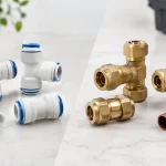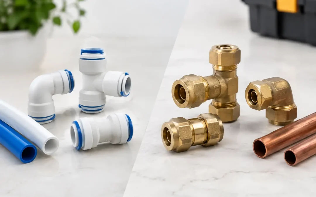
A fitting decision that adds two minutes to installation can save hours of leak tracing later. In the practical comparison of push fittings vs compression fittings, neither connection method is universally better. The correct choice depends on tubing material, pressure range, vibration, temperature, access for service, and how often the connection will be changed during the equipment lifecycle.
For OEM pneumatic assemblies, push-to-connect fittings often provide the fastest path from design to production. For higher-vibration lines, metallic tubing, or applications where mechanical retention is the priority, compression fittings can be the stronger engineering choice. The mistake is treating them as interchangeable because both connect a tube to a port.
How the Two Connection Methods Work
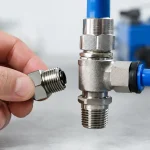
A push fitting, also called a push-to-connect or one-touch fitting, secures tubing when it is inserted into the fitting body. An internal collet grips the outside diameter of the tube while an O-ring creates the primary seal. To release the tube, the technician presses the release ring or collet and withdraws the tubing.
This design is common in pneumatic automation because it eliminates the need to thread a nut, set torque, or carry additional assembly tools. It is particularly effective with properly sized polyurethane, nylon, polyethylene, and other approved pneumatic tubing.
A compression fitting uses a nut and one or more ferrules, often called sleeves or olives, that are mechanically tightened around the tube. As the nut is tightened, the ferrule compresses against the tube and fitting body, producing a sealed, mechanically retained connection. Compression fittings are widely used with copper, stainless steel, and other metal tubing, although compatible designs are available for certain thermoplastic tubes.
The essential distinction is simple: push fittings depend on an internal gripping and sealing mechanism activated by tube insertion, while compression fittings depend on controlled mechanical deformation created by tightening the nut.
Push Fittings vs Compression Fittings in Production
For most standard pneumatic circuits, installation speed is the primary reason to specify push fittings. A clean, square-cut tube can be inserted in seconds. On a machine with dozens or hundreds of air lines, this can reduce assembly time substantially and simplify field replacement when a tube is damaged.
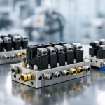
Push fittings also support compact machine design. Elbows, tees, manifolds, bulkhead connections, flow-control combinations, and miniature fittings are available in layouts that help engineers route tubing through constrained enclosures. A technician can disconnect and reconnect tubing without dismantling an adjacent portion of the circuit.
Compression fittings take more time to install because every connection must be assembled and tightened correctly. That time can be justified where the application has persistent vibration, elevated temperatures, metallic hard line, or a connection that should remain undisturbed for long service intervals. Once properly installed, a compression fitting provides high mechanical holding strength and does not rely on an elastomeric O-ring as the primary tube seal.
That difference matters on mobile equipment, near compressors, on machinery with repeated impact loading, or in industrial environments where tubing may be pulled, rubbed, or subjected to heat. A push fitting can perform reliably in many of these environments, but it must be selected for the actual duty cycle and protected from excessive side loading.
Installation Quality Determines Fitting Performance
Many fitting failures begin before air is applied. A push fitting cannot compensate for tubing that is oval, deeply scratched, poorly cut, or outside the specified diameter tolerance. The tube should be cut squarely with a dedicated tubing cutter, not crushed with side cutters. Burrs, angled ends, and surface damage can compromise the O-ring seal or prevent the collet from gripping consistently.
Tube insertion depth matters as well. If the tube is not fully seated, it may seal initially but release or leak when the line moves. Technicians should confirm that the tube has reached the internal stop, then perform a light pull test. The test should verify collet engagement without applying enough force to damage the connection.
Compression fittings demand their own discipline. Over-tightening can deform soft tubing, damage threads, distort ferrules, and make later service difficult. Under-tightening can create a leak path or allow tube movement. Follow the fitting manufacturer’s assembly procedure, especially where a specific number of turns from finger-tight is required.
With metal tubing, correct preparation is equally important. The tube must be cut cleanly, deburred inside and out, aligned with the fitting body, and fully inserted before tightening. A misaligned tube can create a leak even when the nut feels tight. Tightening harder is not a reliable fix.
Choose by Tubing, Environment, and Service Strategy
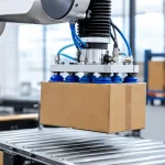
The tubing itself often makes the selection clear. Flexible polyurethane and nylon pneumatic tube are natural matches for push-to-connect fittings. Their use in actuator circuits, valve islands, pick-and-place equipment, packaging machines, and robotic end effectors makes fast installation and easy rerouting highly valuable.
Metal tubing generally favors compression connections. Copper and stainless steel tube are used where heat, chemical exposure, mechanical protection, or dimensional stability exceed what standard pneumatic polymers can provide. In these installations, compression fittings offer a connection method aligned with the tube’s strength and intended service life.
Environmental conditions deserve the same weight as pressure ratings. A fitting rated for the system’s operating pressure may still be a poor selection if it faces aggressive washdown chemicals, high radiant heat, UV exposure, continual vibration, or contamination around the release mechanism. Material selection matters: brass, nickel-plated brass, stainless steel, engineering polymer, and seal material each have limits that should match the application.
For example, a standard push fitting may be ideal inside a protected electrical enclosure feeding compact cylinders. The same fitting may not be the preferred option on an exposed line near a heat source or on a vibrating machine frame. An all-metal compression fitting with compatible tubing may deliver a more durable result there, even if installation takes longer.
Leak Troubleshooting: Find the Failure Mode First
When a push fitting leaks, replacing the fitting before inspecting the tube often wastes time. Remove the tube and check the sealing area for a groove, abrasion, flattening, discoloration, or an uneven cut. Cut back to undamaged material if sufficient tube length remains, then reinsert it fully. If the tubing has hardened or lost its round profile, replace the section rather than forcing a marginal repair.
A leak at the threaded port is a separate issue from a leak at the tube connection. Verify thread type before installation. NPT, BSPP, BSPT, metric, and other threads are not interchangeable. Use the appropriate sealing method for the thread form, and avoid applying excessive thread sealant where it can enter a pneumatic circuit and contaminate valves or instruments.
Compression fitting leaks should be diagnosed by locating the exact leak point. Leakage at the nut may indicate improper assembly, a damaged ferrule, misalignment, or tube surface damage. Leakage at the port threads points to a thread-sealing issue, not necessarily a failed compression joint. Disassembling and reusing components without inspecting the ferrule can create recurring problems.
Pressure cycling can expose marginal assemblies that passed an initial static test. Test repaired circuits at operating pressure, observe them through multiple cycles, and check for tubing movement at the fitting. In automated equipment, this is more meaningful than a quick low-pressure soap test performed before the machine is put back into service.
Design Trade-Offs Engineers Should Specify Early
For new equipment, define the connection strategy before releasing the pneumatic layout. Mixing fitting families without a reason can complicate assembly instructions, spare-parts inventory, and maintenance training. Standardizing on a controlled set of tube sizes, thread types, and fitting materials improves purchasing consistency and reduces the chance of field substitutions.
Push fittings are usually the better specification when assembly speed, compact routing, frequent modifications, and rapid service are the main priorities. They are highly effective in well-managed pneumatic systems using compatible tubing and properly supported line runs.
Compression fittings are usually the better specification when the line is intended to remain fixed, when tubing is metallic, or when vibration and mechanical stress make retention the central concern. They require more installation control, but that investment can be appropriate for demanding duty.
There are also hybrid systems. A machine may use push fittings throughout its protected pneumatic control cabinet and compression fittings on rigid external runs near heat, vibration, or mechanical exposure. This approach avoids overengineering simple connections while protecting the sections that carry the highest risk.
Build Reliability Into the Connection
The lowest-cost fitting is not the one with the lowest unit price. It is the fitting that installs correctly, holds pressure through the expected duty cycle, and can be serviced without creating new downtime. Select fittings as part of the complete air circuit, including tube material, pressure, temperature, motion, contamination exposure, and technician access.
For high-performance pneumatic systems, connection reliability is designed in long before the first leak check. Specify the fitting method that matches the line’s real operating conditions, then give the installer the correct tubing, preparation tools, and assembly standards to make that choice perform.