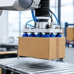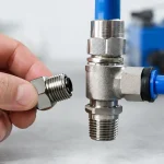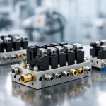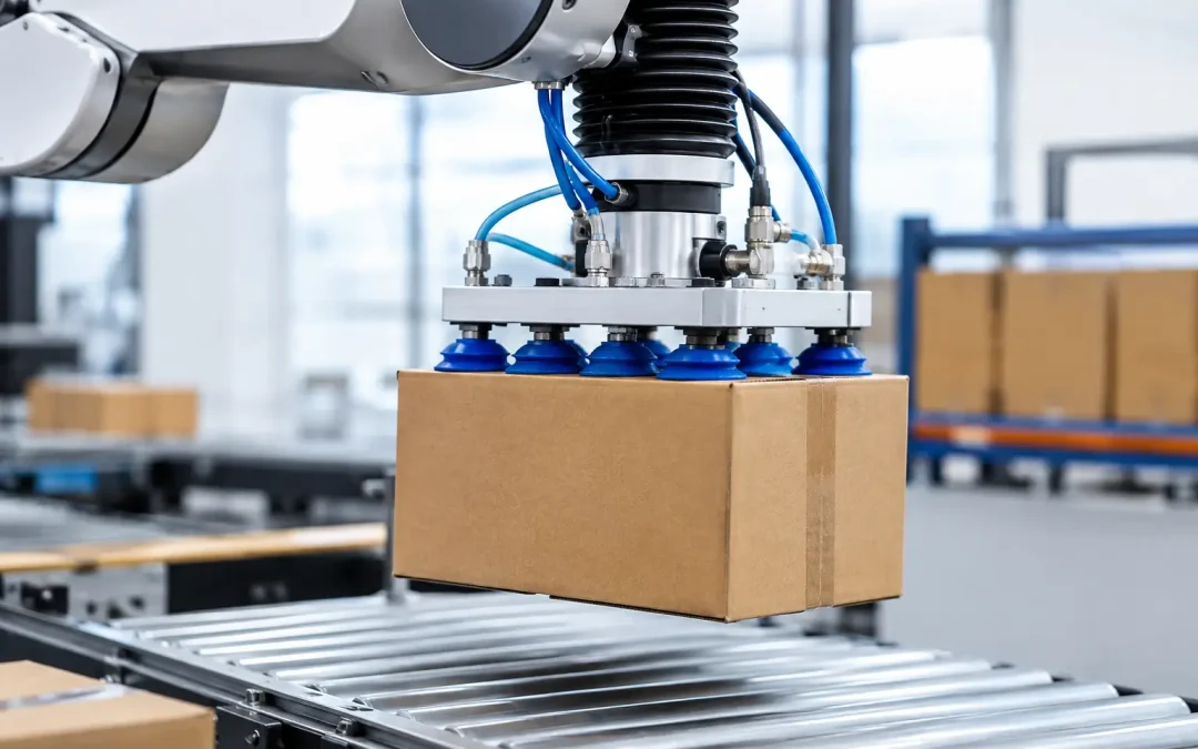
A carton that releases halfway through a palletizing move is rarely a “bad vacuum cup” problem. More often, it is a system problem: undersized flow capacity, an ignored leak path, poor cup contact, or valve placement that adds milliseconds until they become lost production. This vacuum handling system guide focuses on the decisions that determine whether an end effector picks consistently at production speed or becomes the cell’s recurring source of stops.
Start With the Workpiece, Not the Vacuum Generator
Vacuum handling begins with the load, its surface, and the actual motion profile. Calculate the mass of the workpiece plus any tooling carried by the cups, then account for acceleration, deceleration, robot orientation, and the effect of surface contamination. A part lifted vertically at a controlled speed is one case. A part picked from a conveyor, accelerated hard, rotated, and placed at an angle requires a different safety margin.
Cup holding force is driven by effective cup area and the pressure differential between atmospheric pressure and the vacuum level at the cup. In practical terms, larger effective area and deeper vacuum create more holding force. But deeper vacuum is not automatically the right answer. Many material-handling tasks need fast airflow to establish contact and evacuate a small volume, not the highest possible final vacuum level.
Porous corrugate, textured plastic, woven materials, and uneven castings leak continuously. For these applications, select a source that can sustain flow under leakage rather than relying on a published maximum vacuum figure. Smooth glass, sealed sheet metal, and rigid plastic usually reward a different approach: good cup contact, fast local evacuation, and controlled release.
A useful sizing process considers four operating conditions:
- The maximum lifted load, including dynamic forces and any off-center center of gravity.
- The minimum expected vacuum at the cup after hose losses and normal leakage.
- The number of cups that may contact imperfectly during a real pick.
- The required pick confirmation and release times at the target cycle rate.
Do not size around ideal samples. Production surfaces change with dust, oil, temperature, carton quality, tooling wear, and product variation. A system with no allowance for those conditions may work during commissioning and fail on the night shift.
Select Cups for Surface Contact and Motion
Cup selection is often treated as a diameter decision. Diameter matters, but cup material, lip geometry, stroke, and mounting compliance frequently matter more. A flat cup can grip a smooth, rigid panel with high stability. It can also lose seal immediately on a bowed carton or a stamped panel with local variation.
Bellows cups add compliance and can compensate for height differences, angled surfaces, and uneven pickup points. Their trade-off is movement under load. In high-acceleration robotic applications, excessive bellows compression can allow the load to shift, which can reduce placement accuracy or introduce oscillation. Short-stroke bellows designs are often a practical middle ground when the surface varies but the end effector needs controlled positioning.
Material selection deserves the same attention. Nitrile is commonly suitable for general industrial use and oily surfaces. Silicone can be useful where temperature resistance or non-marking contact matters, while polyurethane often provides strong wear resistance for abrasive handling. Food, pharmaceutical, and sensitive electronic applications may require material choices based on compliance, extractables, static behavior, or traceability. The right cup material depends on the environment as much as the part.
Cup layout should prevent the load from pivoting. Place cups as far apart as the part geometry allows and support the anticipated center of gravity. If a large panel can flex, multiple smaller cups with level compensation may outperform one oversized cup. If product formats change frequently, modular cup manifolds and adjustable mounting brackets reduce changeover time without rebuilding the end effector.
Choose the Vacuum Source by Flow, Efficiency, and Duty Cycle
Compressed-air ejectors are compact, fast, and easy to place close to the tool. That proximity is valuable because hose volume directly affects evacuation time. An ejector at the end effector can establish vacuum faster than a centralized unit connected through long tubing, particularly when a robot moves through a large envelope.
The trade-off is compressed-air consumption. A continuously operating ejector can become a significant utility cost, especially on porous workpieces. Multi-stage ejectors may improve performance where high suction flow is needed, while vacuum pumps are often more economical for high-duty, centralized applications with stable demand. The correct choice depends on total cycle time, leak rate, required response time, available air quality, and the cost of compressed air at the facility.
For many cells, a controlled ejector with an air-saving function is the practical answer. Once the required vacuum threshold is reached, the unit reduces or stops air consumption and reactivates when vacuum falls below the set point. This approach works well when the part seals reasonably well. It is less effective when the workpiece leaks so heavily that the ejector must run continuously.
Avoid placing a high-flow source far upstream and expecting tubing to solve the problem. Long, undersized lines restrict flow and add volume that must be evacuated every cycle. Use the shortest practical vacuum path, size tubing for flow demand, and position control valves near the end effector when response time matters.
Build Controls That Detect a Bad Pick Early
A vacuum switch is not merely a confirmation device. Correctly configured, it is a quality gate that prevents a robot from traveling with an uncertain load. Set the pickup threshold based on measured production conditions, not the deepest vacuum achieved during a perfect test pick. If the threshold is too high, normal variation creates nuisance faults. If it is too low, the system confirms marginal picks that fail during motion.
Use separate logic for “part present” and “safe to move” when the application justifies it. A cup may detect contact before the system has sufficient holding force for full acceleration. For critical operations, the PLC can require a stable vacuum signal for a short verification period before issuing the move command. That small delay is often less costly than a dropped product, damaged fixture, or manual recovery event.
Vacuum decay monitoring adds another layer of protection. After vacuum is established and the source is reduced or isolated, a rapid pressure rise can indicate a leaking cup, cracked hose, blocked filter, or poorly seated part. This is especially useful in unattended palletizing, packaging, and machine tending cells where a single bad pickup can create a jam downstream.
For multiple-cup tooling, consider zoned circuits or check valves. A check valve can preserve vacuum at sealed cups when one cup lands on a hole, edge, or surface defect. Zoned control allows the tool to adapt to different product sizes, but it adds valves, I/O, diagnostics, and potential leak points. Use that complexity where format flexibility or part variation creates a measurable return.
Treat Release as a Controlled Function
A tool that grips reliably but releases inconsistently can still limit throughput. Vacuum-off alone may not release smooth or lightweight material quickly because residual vacuum remains in the cup and tubing. Blow-off introduces a controlled positive-air pulse to break the seal and clear the part.
Too much blow-off can shift lightweight products, create noise, or blow contaminants onto sensitive surfaces. Too little adds release delay and may cause double picks. Set the pulse pressure and duration at the tool, then verify release across the full range of product conditions. A short, targeted pulse is generally more effective than flooding the circuit with air.
Exhaust routing also matters. Ejector exhaust can carry noise, oil mist, or fine debris into the work area. In clean processes or enclosed automation equipment, use appropriate silencers and consider where exhaust is directed. Restrictive silencers, however, can reduce ejector performance, so verify the complete assembly rather than evaluating the generator alone.
Troubleshoot by Measuring the Pressure Curve
When pickup becomes unreliable, technicians often replace cups first. Inspecting cups is appropriate, but the fastest diagnosis comes from observing vacuum versus time at or near the tool. A slow ramp to vacuum points toward insufficient flow, excessive tubing volume, clogged filtration, or a restricted fitting. A normal initial pull followed by rapid decay suggests leakage, cup damage, a loose fitting, or a faulty check valve.
If the vacuum level is adequate at rest but parts drop during motion, investigate dynamic loading, cup layout, cup compression, hose movement, and acceleration settings. The issue may be mechanical rather than pneumatic. If failures occur only after maintenance, confirm that tubing lengths, fitting sizes, generator orientation, and pressure regulator settings match the approved build.
Compressed-air quality is another frequent contributor. Water, oil carryover, and particulate contamination can foul ejectors, damage seals, and create inconsistent valve performance. Proper filtration and regulated supply pressure protect the vacuum circuit and make performance repeatable. The system should have accessible gauges or electronic pressure feedback so a technician can distinguish a supply-air problem from a vacuum-side problem quickly.
Design for Service Before the Cell Is Running
A high-performance vacuum tool should also be serviceable under production pressure. Put filters where they can be inspected, use labels that identify zones and valve functions, and leave enough tubing slack for maintenance without allowing hoses to snag during motion. Standardizing cup threads, fitting sizes, and valve interfaces simplifies spare-parts inventory across similar cells.
For OEMs and integrators, configured vacuum assemblies can reduce build variation and commissioning time. VidoAir supports vacuum components alongside pneumatic controls, air preparation, tubing, and fittings, which helps keep the vacuum circuit aligned with the rest of the machine’s air-management architecture.
The best vacuum handling systems are not defined by the highest vacuum reading. They are defined by predictable grip, fast confirmation, controlled release, and diagnostics that identify a weak pick before it becomes lost uptime.