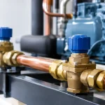
A refrigeration circuit can lose capacity long before a technician sees frost, hears a complaint, or receives a high-temperature alarm. A valve that is slightly undersized, installed against its flow direction, or paired with the wrong coil can create pressure drop, unstable control, and compressor risk. For OEMs and maintenance teams, refrigeration valves are not commodity parts. They are control points that determine whether a system cycles cleanly, protects the compressor, and holds temperature under changing load.
Start with the failure mode, not the valve catalog
The fastest way to choose the wrong valve is to begin with port size alone. Nominal connection size matters, but refrigerant type, required capacity, pressure differential, fluid condition, coil voltage, ambient temperature, and duty cycle all shape the correct selection.
For example, a liquid-line solenoid valve may need to support pump-down control. In that application, a normally closed valve shuts when the thermostat is satisfied, allowing the compressor to pump refrigerant from the low side into the receiver or condenser. The low-pressure control then stops the compressor. If the valve leaks internally, the evaporator pressure can rise during the off cycle, causing short cycling or difficult pump-down.
A suction-line valve presents a different decision. Pressure drop becomes especially consequential because every restriction on the suction side can reduce effective compressor capacity and increase energy use. A valve that looks acceptable by connection size may be too restrictive at design mass flow, particularly on a low-temperature system where vapor density is low.
The application also determines whether a direct-acting or pilot-operated design is appropriate. Direct-acting solenoid valves can operate with zero differential pressure, making them useful where pressure conditions are limited or uncertain. Pilot-operated valves generally support greater capacities, but they require adequate pressure differential to open and remain open reliably. That trade-off should be confirmed at both normal operating conditions and the lowest expected load.
Refrigeration valves: match the design to the circuit
A practical selection process separates valve function from valve construction. First, define what the valve must accomplish in the circuit. Then verify that the body, seat materials, coil, and connection configuration are suited to the refrigerant and operating environment.
Solenoid valves for shutoff and pump-down
Solenoid valves are commonly applied where automatic on-off control is needed. In liquid lines, they support pump-down, prevent migration during off cycles, and isolate sections of a circuit. In hot-gas applications, they route discharge gas for defrost or capacity control. These are very different duties, even when the valve bodies appear similar.
For liquid service, select for low pressure drop at the system’s actual capacity, not only its maximum nameplate rating. For hot-gas defrost, confirm that the valve is rated for discharge temperature and pressure, and account for the force created when hot gas enters a cold coil. A slow or leaking valve can extend defrost time, raise box temperature, and produce uneven coil clearing.
Coil selection deserves equal attention. Verify voltage, AC or DC supply, frequency where applicable, connector style, enclosure needs, and continuous-duty temperature rating. Coil overheating is often blamed on an electrical problem, but the root cause may be mechanical. A contaminated pilot port, incorrect pressure differential, or debris holding the plunger off its intended position can make a coil run hotter than expected.
Check valves for flow direction and pressure stability
Check valves prevent reverse flow, but their influence extends beyond basic isolation. In parallel compressor circuits, defrost arrangements, heat reclaim systems, and multi-evaporator designs, reverse flow can cause oil movement problems, unwanted pressure equalization, or refrigerant migration.
Cracking pressure is the key specification. Too little cracking pressure can permit unwanted flow under minor pressure changes. Too much cracking pressure adds restriction and can create control instability. The best setting depends on the pressure difference available during normal operation and the consequence of reverse flow during off cycles, defrost, or compressor staging.
Expansion and regulating valves for stable capacity control
Thermostatic expansion valves, electronic expansion valves, and pressure-regulating valves have different control roles, but all require stable inlet conditions and clean refrigerant. A regulating valve cannot compensate indefinitely for a plugged filter drier, flashing liquid upstream, or a poorly located pressure sensing point.
When troubleshooting unstable superheat or evaporator starvation, do not assume the expansion valve is defective. Check liquid subcooling, pressure drop across upstream components, distributor condition, bulb mounting or sensor placement, and whether the system load has changed beyond the valve’s control range. Replacing a valve before confirming these conditions can repeat the same failure with a new part.
Sizing errors that create hidden restrictions
Valve sizing should be based on manufacturer capacity data for the refrigerant and operating condition, not a generic flow estimate. Capacity changes significantly with evaporating temperature, condensing pressure, liquid temperature, and allowable pressure drop. A valve sized for medium-temperature R-404A conditions may not deliver acceptable performance in a low-temperature R-448A application, even if the line connection matches.
The usual temptation is to oversize. That is not always safer. An oversized pilot-operated solenoid may struggle to operate at low load if differential pressure falls below its requirement. An oversized regulating valve may hunt because small changes in flow produce outsized changes in system response. The goal is usable control authority across the operating envelope, not the largest available orifice.
Pay close attention to pressure drop across liquid-line valves. A modest drop may be harmless in a system with generous subcooling. In a long liquid line, high ambient environment, or system already operating close to flashing conditions, that same drop can send a mix of liquid and vapor to the expansion device. The result is reduced capacity, erratic superheat, and a service call that may be misdiagnosed as an expansion-valve issue.
Installation details that determine valve life
Correct valve selection can still fail in the field when installation discipline is weak. Flow arrows must match the actual refrigerant path for the operating mode. This is especially important in heat pumps, reverse-cycle systems, and circuits with hot-gas bypass, where flow direction may not be obvious from a simplified piping sketch.
Protect the valve body from excessive heat during brazing. Remove or protect the coil as specified by the manufacturer, use proper heat control practices, and avoid directing flame toward seals, seats, or pilot assemblies. Contamination is another common cause of early failure. Nitrogen purging during brazing reduces oxide scale that can later block pilot ports or prevent a valve from seating.
Install strainers or appropriate filtration where the circuit and valve design call for it. A strainer is not a substitute for clean installation, and it introduces its own pressure drop, but it can protect sensitive pilot passages in systems where debris risk is credible. Service access matters as well. A valve that cannot be safely isolated, electrically tested, or replaced without opening a large section of the circuit turns a small repair into extended downtime.
Diagnose before replacing refrigeration valves
A valve that will not open, will not close, or appears to restrict flow should be tested as part of the circuit. Start with the simple checks: confirm the control signal at the coil, verify coil resistance against the expected range, inspect connectors and terminals, and listen or feel for actuation when the command changes. Electrical energization alone does not prove that the valve has shifted internally.
Next, compare pressures and temperatures upstream and downstream under the relevant operating condition. A closed liquid solenoid should produce a meaningful change during pump-down. A valve believed to be open but showing an unexpected pressure drop may be undersized, partially restricted, installed incorrectly, or operating outside its differential-pressure range. Frost patterns can be useful clues, but they are not proof of a failed valve without pressure and temperature data.
If a valve leaks closed, confirm that the issue is truly internal leakage rather than a bypass path elsewhere in the piping. In multi-circuit equipment, parallel paths, leaking compressor valves, and incorrect control sequencing can imitate solenoid leakage. Replacing components based on symptoms alone increases cost without improving reliability.
For demanding refrigeration equipment, component quality and support availability are part of the maintenance strategy. VidoAir supplies factory-direct refrigeration solenoids and related control hardware for buyers who need dependable replacement options and application-focused technical support.
A well-specified valve should disappear into normal operation: it opens when commanded, seals when required, and adds no unnecessary restriction. Document the circuit conditions when a valve is selected or replaced. That record gives the next technician a baseline, helps procurement source the correct equivalent, and turns a recurring service problem into a controlled engineering decision.