
A vacuum handling example becomes useful when it exposes the decisions that determine whether a cell runs reliably at 20 picks per minute or stops every few cycles. Consider an end-of-line system that picks sealed corrugated cartons from a conveyor, rotates them 90 degrees, and places them into a palletizing pattern. The cartons appear simple, but their recycled board surface, variable flap stiffness, occasional dust, and changing product weights make vacuum selection an engineering task rather than a catalog checkbox.
This application calls for more than calculating a theoretical lifting force. The gripper must tolerate imperfect contact, hold the load through acceleration, detect a missed pick before the robot moves, and recover quickly when a carton is not presented correctly. The following approach shows how to specify the vacuum circuit and diagnose the problems that commonly appear after commissioning.
Vacuum Handling Example: Picking Sealed Cartons
Assume the cell handles cartons weighing up to 18 lb. The robot approaches from above, picks the carton from a moving conveyor, accelerates into a turn, and releases it on a pallet. Carton dimensions vary, but each top panel provides enough flat area for four suction cups.
A common first attempt is to select cups based only on the carton weight. That calculation may produce an acceptable result on a smooth, new carton, then fail on a porous recycled-box surface. Vacuum gripping force depends on the pressure differential and the effective sealed area. If air leaks through the carton surface or around a warped panel, the available differential pressure drops and so does holding force.
For a vertical lift, engineers often start with the relationship:
Holding force = pressure differential x effective cup area
That is only the starting point. For a robot that accelerates, turns, and may experience an emergency stop, apply a safety factor that accounts for dynamic loading, surface variation, and leakage. A factor of 2 is often a reasonable minimum for stable, clean carton handling. A higher factor may be necessary when cartons are dusty, porous, wet, or subject to aggressive robot motion.
Four cups also provide redundancy. If one cup lands over a carton seam or a damaged area, the remaining cups may still retain the load. That redundancy only works when the vacuum circuit isolates a leaking cup. Without isolation, one poorly sealed cup can consume enough flow to lower vacuum across the entire gripper.
Selecting the Cups and Contact Geometry
For corrugated cartons, bellows cups are frequently the better choice because they accommodate small height differences and uneven top panels. A flat cup may provide more stable lateral positioning on a rigid, smooth surface, but it can lose contact when the carton crown varies. The cup material matters as well. Nitrile is often a practical general-purpose choice, while silicone may be better where temperature resistance or softer contact is needed. Material selection should also consider marking, washdown exposure, and the presence of oils or release agents.
Cup placement should keep the load balanced around the robot tool center point. Placing all cups near the carton edges can increase resistance to tipping, but it may put a cup on a flap seam. A better layout places cups over structurally supported areas while keeping enough spacing to resist rotation during the robot turn.
Do not assume that a larger cup always solves the problem. Larger cups generate more theoretical force, but they require more surface area, can bridge over local defects, and may release more slowly. On lightweight cartons with weak top panels, excessive vacuum can also deform the board and create an inconsistent seal. The right cup is the one that maintains contact across real carton variation without damaging the package.
Build the Vacuum Circuit for Leakage, Not Ideal Conditions
A vacuum generator must provide enough flow to overcome expected leakage and enough vacuum level to meet the required holding force. These needs can pull in different directions. High vacuum level favors holding force on a well-sealed part. Higher flow capacity helps maintain performance on porous or imperfect surfaces. Cartons usually require a design that respects both.
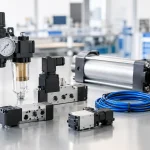
A decentralized ejector mounted close to the gripper can reduce response time and tubing losses. It is a strong option for fast robotic cells where each tool needs independent control. A centralized vacuum pump can make sense for multiple stations or high-duty-cycle installations, particularly when energy management and service access are priorities. Neither approach is automatically superior. The best arrangement depends on cycle rate, required flow, available compressed air, noise limits, and the cost of downtime.
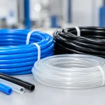
For this carton cell, use a separate vacuum path for each cup or cup pair, fitted with check valves or vacuum-saving valves. Add a small vacuum reservoir near the tool if the robot must retain the carton briefly during a pressure dip or if line length cannot be avoided. Keep tubing short and appropriately sized. Restrictive tubing can make a correctly sized generator look weak because vacuum builds too slowly at the cup.
A properly selected filter is equally important. Corrugated dust is abrasive and persistent. If debris reaches the ejector or vacuum sensor, performance drifts and troubleshooting becomes unnecessarily difficult. Install filtration where technicians can inspect and service it without removing the entire end effector.
Verify the Pick Before Motion Begins
The robot should not rely on a timer alone to decide that a carton is attached. Install a vacuum switch or analog vacuum sensor and use it as a permissive signal. After the cups contact the carton and vacuum turns on, the controller should wait for the setpoint before commanding the high-speed move.
The setpoint must be validated during production trials. If it is too low, the system may move a marginally gripped carton. If it is too high, normal variation in board porosity can create nuisance faults. A useful control strategy uses two thresholds: one level confirms pickup, while a lower level triggers a controlled fault response if vacuum falls during transport.
The response to a failed pickup matters as much as detection. The robot should stop or return safely, release vacuum, and request a new carton presentation rather than continuing toward the pallet with an uncertain load. This prevents dropped cartons, tool collisions, and damaged pallet patterns.
Commission the Tool With Production-Level Variation
Bench testing a single sample carton is not validation. Run trials with the lightest and heaviest cartons, fresh and recycled board, cartons from different suppliers, slightly damaged surfaces, and expected conveyor speed variation. Test the worst reasonable acceleration profile, not only a slow demonstration move.
Watch vacuum level from cup contact through placement. A stable curve that reaches the pickup threshold quickly and remains well above the fault limit indicates a healthy system. A gradual decline after pickup points to leakage, a contaminated cup lip, porous material, or inadequate flow. Slow pull-down usually points to undersized tubing, excessive volume, a restricted filter, or insufficient generator capacity.
Also inspect the release phase. If cartons stick after vacuum is switched off, add controlled blow-off or revise the cup material and geometry. Blow-off improves release consistency, but too much pressure can shift a carton during placement or create unnecessary compressed-air use. Tune it to separate the cup cleanly, not to launch the load.
Troubleshoot the Failures That Affect Throughput
When a carton drops during a robot turn, the temptation is to increase vacuum pressure or install a larger generator. Start with evidence instead. If the vacuum signal falls sharply only during rotation, inspect cup placement, lateral loading, and carton flex. The tool may be imposing shear force that the cups were never intended to resist. Repositioning cups or reducing acceleration can solve a problem that added vacuum cannot.
If failures occur randomly across shifts, inspect air quality, filter condition, cup wear, and changes in carton stock. A cracked tube or worn cup lip may only leak when the tool flexes. If the generator has adequate supply pressure at idle but not during multiple simultaneous picks, measure pressure at the device under operating demand. Undersized air preparation hardware or distribution piping can starve an otherwise correct vacuum circuit.
If one cup consistently fails, isolate it during testing. Check for a seam, label edge, warped panel, or mechanical interference at the point of contact. Vacuum systems are sensitive to small physical details, and those details are usually easier to correct than a broad redesign.
Specify for Maintainability as Well as Force
A high-performance vacuum end effector should give maintenance teams clear access to cups, filters, sensors, fittings, and isolation valves. Standardizing cup sizes and spare parts reduces recovery time. Labeling each vacuum zone and sensor input makes troubleshooting faster when the cell is under production pressure.
VidoAir supports this type of configured vacuum handling package with factory-direct components for cups, generators, switches, tubing, fittings, and air preparation. The practical advantage is not simply fewer purchase orders. It is the ability to match the pneumatic circuit, sensing approach, and service parts strategy to the duty cycle of the machine.
Before releasing the design, document the acceptable vacuum range, air supply requirement, cup replacement criteria, filter service interval, and fault response sequence. Those details turn a successful pilot into a tool that keeps performing after thousands of cycles. When the next carton style arrives, the best vacuum handling solution is one with enough engineered margin to adapt without stopping the line.