A pneumatic line can look clean at the point of use and still be starving a cylinder, valve island, or vacuum generator upstream. The question of when should air filters be replaced is not answered by a calendar alone. In a production environment, the correct interval depends on pressure differential, contamination load, filter type, air demand, and the cost of an unplanned performance problem.
For industrial compressed-air systems, a filter element is a wear component with a direct effect on flow capacity and air quality. Waiting until a machine fails is too late. Replacing every element on an arbitrary schedule can be just as inefficient, especially in systems with light duty or unusually clean intake conditions. The practical target is condition-based maintenance supported by a defined maximum service interval.
When Should Air Filters Be Replaced?
Replace a pneumatic air filter element when its pressure drop reaches the equipment manufacturer’s specified limit, when a differential pressure indicator signals restriction, or when contamination has compromised downstream performance. For many general industrial applications, that decision should be verified during scheduled preventive maintenance rather than made only after operators report slow cycle times or inconsistent actuator motion.
A rising differential pressure is usually the most useful trigger. As particulate, rust, compressor carryover, pipe scale, and moisture-related debris collect in the element, resistance increases. The compressor may compensate by running at a higher discharge pressure, but the point of use can still experience lower effective pressure during peak demand. That creates a costly chain reaction: reduced cylinder force, slower actuator speed, unstable regulator performance, and higher energy consumption.
A practical maintenance program uses both a condition limit and a time limit. Replace the element at its rated differential-pressure threshold even if it has been installed only briefly. Replace it at the planned maximum interval even if the indicator has not yet tripped, particularly where contamination control is critical. Filter media can age, seals can harden, and absorbed liquids or aerosols can reduce performance without producing an obvious external warning.
Why Calendar-Only Replacement Intervals Fall Short
A six- or twelve-month replacement schedule is easy to administer, but it does not account for how differently compressed-air systems operate. A packaging machine with short, clean shifts does not load a filter like a foundry process, a mobile heavy-equipment installation, or a plant with an older compressor and corroded distribution piping.
Filter service life changes with the application. High air consumption, frequent pressure cycling, humid intake air, and long pipe runs generally increase contaminant loading. Oil-lubricated compressors can place a greater burden on coalescing elements, especially if separator performance or maintenance has declined. Facilities that have recently modified piping may see a short-term surge of scale and debris as the system stabilizes.
The element type matters as well. A standard particulate filter protects valves and actuators from solid debris and bulk water. A coalescing filter is designed to remove fine aerosols and oil carryover, but its media loads differently and may require closer monitoring. Activated-carbon elements address vapor and odor concerns in specialized applications, yet they have a finite adsorption capacity that a pressure-drop reading alone may not reveal.
That is why critical applications need service criteria matched to the filter’s function. A moderate pressure drop may be acceptable in a general utility air line, while a small change in air quality may be unacceptable before instrumentation, paint equipment, food-related packaging equipment, or sensitive pneumatic controls.
Signs a Pneumatic Filter Element Is Restricting Flow
Pressure gauges and differential indicators provide the strongest evidence, but technicians should also recognize the operating symptoms of a loaded filter. These symptoms can overlap with regulator, compressor, valve, and tubing problems, so they should prompt measurement rather than an automatic filter replacement.
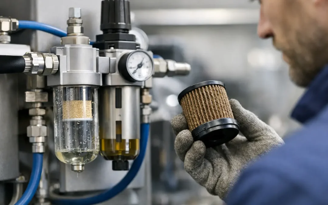
Watch for these patterns when inspecting an FRL assembly or remote filter housing:
- A noticeable pressure difference between the filter inlet and outlet, especially during high-flow machine cycles
- Cylinders that slow down, lose end-of-stroke force, or show inconsistent timing under load
- Increased compressor run time or a need to raise system pressure to maintain production performance
- Frequent moisture accumulation in bowls, downstream contamination, or evidence of oil where it should not be present
- A clogged-element indicator, damaged bowl, degraded seal, or filter media that appears discolored or saturated during service
Do not treat low downstream pressure as proof that the filter is at fault. A regulator setpoint issue, undersized port, partially closed isolation valve, undersized tubing, excessive fitting restrictions, or demand that exceeds compressor capacity can produce similar symptoms. Measure pressure at the filter inlet and outlet while the machine is consuming air. A static check with no flow can hide the restriction that matters most.
Set Service Intervals by Filter Stage and Air Quality Risk
Most pneumatic systems benefit from staged filtration rather than asking one element to handle every contaminant. A typical arrangement may include a water separator or particulate prefilter near the compressor receiver, finer filtration at distribution points, and point-of-use filtration for sensitive equipment. Each stage should have its own inspection and replacement logic.
Particulate filters
Inspect particulate elements regularly where pipe scale, dust, or compressor debris is likely. These elements often show a clear increase in pressure drop as they load. In older plants, replacing a heavily loaded first-stage element without addressing upstream corrosion can create a repetitive maintenance cycle. Drain condensate, inspect the receiver and distribution system, and determine whether the contamination source is active.
Coalescing filters
Coalescing elements protect systems from fine liquid aerosols and oil carryover. Their performance is especially relevant for proportional valves, precision pneumatic controls, vacuum equipment, and processes where oil contamination affects product quality. Replace them based on differential pressure and the manufacturer’s maximum service recommendation. If downstream oil is appearing sooner than expected, inspect compressor lubricant carryover, separator condition, automatic drains, and whether the prefilter is correctly sized.
Activated-carbon filters
Activated-carbon filters are application-specific. They are used where vapor removal is needed, not as a substitute for particulate or coalescing filtration. Because adsorption capacity is consumed by exposure, these elements typically require replacement on a conservative schedule based on air quality requirements and expected vapor load. Waiting for an odor complaint can expose a process to contamination before anyone notices.
Build Replacement Into Preventive Maintenance
The most reliable approach is to make filter inspection part of the same maintenance route used for regulators, lubricators, drains, pressure gauges, and valve manifolds. Record installation dates, element part numbers, operating pressure, observed differential pressure, and the reason for replacement. That history quickly reveals whether an element is failing at a normal rate or whether upstream conditions have changed.
For high-value equipment, add a differential-pressure indicator or transmitter where technicians can see it easily. A visual indicator is often sufficient for a standard machine. A monitored signal may be justified on automated lines where a restricted filter can affect cycle time, reject rates, or robotic handling performance before it causes a full stoppage.
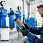
Keep the replacement procedure clean. Isolate and depressurize the assembly, drain the bowl, use the correct seal kit where required, and confirm element orientation. Inspect the bowl for cracking, chemical attack, or impact damage. If a polycarbonate bowl is exposed to oils, cleaners, solvents, or UV conditions outside its rating, replacing only the element does not solve the underlying reliability risk.
Avoid the Costly Habit of Oversizing Pressure
When a machine loses performance, raising the compressor setpoint is a common short-term response. It can also mask a loaded filter and increase energy use across the facility. Every unnecessary pressure increase adds operating cost while placing more stress on components that may already be near their limits.
Instead, verify the actual pressure at the consuming device under peak flow. If the filter is creating unacceptable pressure loss, replace it and reassess. If the replacement element loads unusually fast, investigate the source: compressor intake conditions, failed drains, lubricant carryover, contaminated piping, or an incorrectly selected filter grade. The correction may be a larger filter body, a staged filtration arrangement, or a different air-preparation configuration rather than simply changing elements more often.
For OEMs and maintenance teams, standardizing on clearly specified air-preparation assemblies makes this work faster. Specify flow capacity at the real operating pressure, filtration grade, bowl material, drain type, port size, and acceptable pressure-drop limit. A properly sized, high-performance filter assembly gives technicians a predictable service point instead of a recurring production variable.
Treat filter replacement as a measured reliability decision. A clean element installed at the right time protects the pneumatic components that cost far more to diagnose, rebuild, or replace – and keeps available air pressure where the machine needs it most.