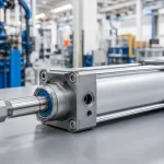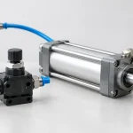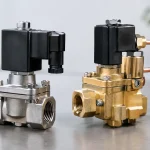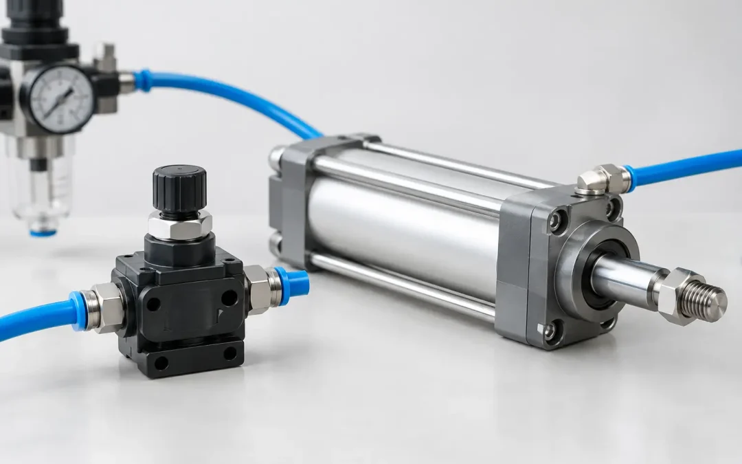
A cylinder that slams at the end of stroke is rarely a cylinder problem. It is usually an air-management problem. When technicians ask, which valve controls cylinder speed, the direct answer is a flow control valve. In most industrial pneumatic circuits, that means a one-way flow control valve, often called a speed controller, installed to meter airflow rather than simply reduce system pressure.
The practical answer needs one qualification: valve placement and the direction being controlled matter as much as the valve itself. A correctly selected flow control can deliver repeatable, stable motion. The same component installed on the wrong port can create stick-slip, runaway extension, poor cycle consistency, or a cylinder that behaves differently as the load changes.
Which Valve Controls Cylinder Speed? Use Flow Control
Cylinder speed is controlled by the rate at which compressed air enters or leaves the cylinder chamber. A flow control valve restricts that airflow through an adjustable needle or orifice. Less airflow means a slower piston speed; more airflow means a faster speed.
For a double-acting cylinder, speed control usually requires attention to both ports. The cap end controls extension behavior, while the rod end controls retraction behavior. A one-way flow control valve combines an adjustable restriction with a check valve. Air flows freely in one direction through the check valve and is restricted in the other direction through the needle setting.
That design gives the machine builder independent control over the speed of each stroke without adding unnecessary pressure loss in the opposite direction. It is the standard choice for clamping, indexing, part transfer, packaging mechanisms, pneumatic slides, and actuator-driven handling equipment.
A directional control valve does not normally set cylinder speed. Its job is to route supply and exhaust air so the actuator extends, retracts, or stops. Likewise, a pressure regulator controls available pressure and therefore cylinder force, but it is not the preferred primary method for setting velocity. Reducing pressure to slow a cylinder often sacrifices force margin and can make motion less consistent when friction or payload changes.
Meter-Out Is Usually the Best Starting Point
For most pneumatic cylinders, meter-out control is the preferred arrangement. In a meter-out circuit, the flow control valve restricts exhaust air leaving the cylinder. Supply air enters the active chamber freely while the air escaping from the opposite chamber is metered.
This creates back pressure on the exhaust side of the piston. That back pressure resists acceleration and gives the system a damping effect, especially when the load could pull, push, or otherwise assist cylinder motion. It is the reason meter-out is commonly used on vertical actuators, rodless cylinders, slide tables, and horizontal axes moving variable loads.
Consider a cylinder extending a fixture against a light load. If the rod-side exhaust is unrestricted, stored air energy can accelerate the piston rapidly, particularly after breakaway friction is overcome. Metering the exhaust forces air to leave at a controlled rate, preventing the cylinder from racing through the stroke.
Meter-out is not a cure for every motion problem. Restricting exhaust too aggressively can create excessive back pressure, slow cycle time, raise air consumption, and prevent a cylinder from reaching its intended end position under load. The correct setting is the lowest restriction that produces controlled, repeatable motion at production speed.
Why meter-in can be less stable
Meter-in control restricts air entering the cylinder chamber while exhaust air leaves freely. It can work well on applications with a consistent resisting load, such as a cylinder pushing against a controlled process force. However, it is generally less stable where the load assists movement.
With an overrunning load, the piston can move ahead of the incoming air. This may cause pressure to drop behind the piston and lead to surging or erratic speed. A vertically mounted cylinder lowering a load is a common example. For this reason, meter-in should be selected deliberately, not simply because the fitting orientation is convenient.
Valve Selection Depends on More Than Port Size
A 1/4-inch flow control valve is not automatically suitable for every 1/4-inch cylinder port. Port thread size describes the connection, not the valve’s usable flow capacity. Engineers should size the valve around the cylinder bore, stroke time, operating pressure, tubing length, and load condition.
An undersized speed controller may limit the cylinder so severely that the desired cycle time cannot be reached. An oversized valve may make adjustment overly sensitive, where a small turn of the needle changes speed dramatically. The usable adjustment range matters as much as maximum flow.
The tubing and fittings also affect the result. Long runs of small-diameter tubing can become the effective restriction in the circuit, leaving little meaningful control at the valve. Mounting flow controls directly at the cylinder ports is usually the best practice because it minimizes the volume of uncontrolled air between the restriction and the actuator.
For high-cycle equipment, choose components built for repetitive adjustment and vibration exposure. A locking adjustment feature helps prevent settings from drifting after commissioning. Metal-body speed controllers, durable seals, and application-appropriate thread configurations are worthwhile when uptime and repeatability are production requirements rather than preferences.
When a Quick Exhaust Valve Is the Better Tool
A quick exhaust valve does not replace a flow control valve, but it solves a related problem. It vents cylinder air locally to atmosphere instead of forcing exhaust to travel back through the directional valve and long tubing runs. This reduces exhaust restriction and can substantially increase cylinder speed.
Quick exhaust valves are useful when a large-bore cylinder must retract or extend rapidly, when tubing distance to the control valve is significant, or when cycle time is constrained by exhaust capacity. They are often paired with flow controls, not used alone. The quick exhaust provides high-capacity discharge, while a correctly arranged speed control establishes the final motion rate.
Use caution with the combination. A quick exhaust can make an actuator unexpectedly aggressive if the flow control is bypassed or installed in a way that does not restrict the intended exhaust path. Test motion at reduced pressure during commissioning, then increase to normal operating conditions while verifying that the load, tooling, and guards are ready for full-speed operation.
Troubleshoot the Whole Motion Circuit
If adjusting the flow control does not change cylinder speed, the restriction may be installed backward, bypassed by its check valve, or overwhelmed by another limitation. Confirm the directional valve is fully shifting and that its exhaust ports are not blocked by undersized silencers, contamination, or ice in cold environments.
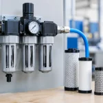
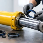
Cylinder condition matters as well. Internal seal wear can cause bypass leakage and weak speed control. Side loading on the rod can increase friction and create slow breakaway followed by sudden movement. Water, oil carryover, or debris in the compressed-air supply can foul the fine adjustment passage in a speed controller. Proper filtration and air preparation protect motion accuracy as well as component life.
For vertical cylinders or loads that can move when air is lost, do not rely on a standard flow control valve as a safety device. Use appropriately engineered load-holding, rod-locking, counterbalance, or mechanical safety measures based on the risk assessment. Speed control manages normal motion. It is not designed to secure a suspended load during a pressure failure.
A Practical Setup Sequence
Start with both flow controls set open enough to prevent severe restriction. Run the actuator at reduced supply pressure, observe extension and retraction independently, and adjust the exhaust-side control for each direction in small increments. Once the target speed is reached, verify several consecutive cycles with the real payload, not an unloaded test fixture.
Then check the machine at its expected operating pressure, temperature, and cycle rate. A circuit that looks stable during a slow bench test may behave differently after the valves warm up, production air demand rises, or the payload changes. Record the final settings and component orientation for maintenance teams.
VidoAir flow control and pneumatic valve selections support this kind of application-level tuning, from standard replacement hardware to configured motion-control assemblies for demanding automation systems. The goal is not merely to slow a cylinder. It is to produce controlled motion that stays controlled through the operating conditions the machine will actually see.
When cylinder speed becomes inconsistent, start at the exhaust path: verify meter-out orientation, valve capacity, tubing volume, and load behavior before reducing pressure or replacing the actuator. That sequence usually identifies the real restriction and leads to a faster, more durable correction.