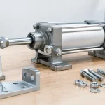
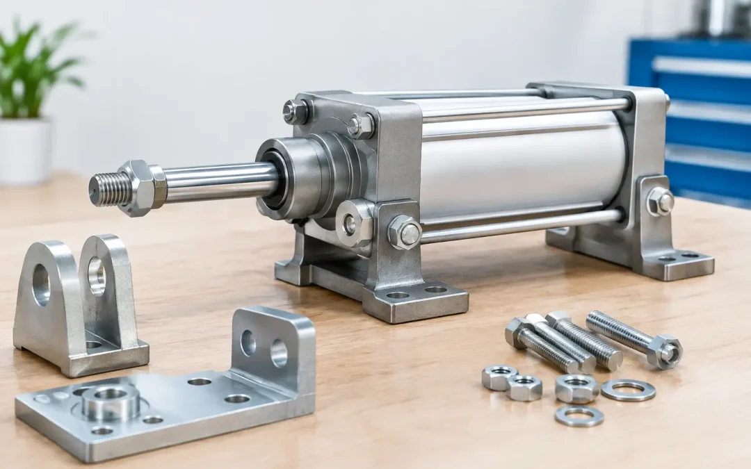
A cylinder can have the correct bore, stroke, valve, and air supply and still fail early because the mounting arrangement turns it into a structural member it was never designed to be. This pneumatic cylinder mounting guide focuses on the installation decisions that protect rod bearings, prevent binding, and keep production equipment moving at the commanded speed.
For OEMs, integrators, and maintenance teams, mounting is not a hardware afterthought. It determines how force enters the machine frame, whether the cylinder can pivot through its travel, and how much side load reaches the rod and piston. A few millimeters of misalignment may not stop a new machine from cycling, but it can produce seal wear, inconsistent end positions, rising breakaway pressure, and unplanned downtime later.
Start With the Load Path, Not the Mounting Holes
Before selecting a bracket, define what the actuator must move and how the load behaves throughout the stroke. Cylinder thrust is axial. The most reliable installation keeps the working force centered on the rod axis from extension through retraction.
A rigidly mounted cylinder is generally the right choice when it pushes or pulls a guided load in a straight line. Tie-rod mounts, front flange mounts, rear flange mounts, and center trunnions can all provide a stable reference to the machine structure. The key is that the driven member must have its own linear guidance. A cylinder rod is designed to transmit force, not to compensate for a carriage that racks, sags, or travels on worn rails.
If the driven mechanism moves through an arc, use a pivoting arrangement. Clevis mounts, rear trunnions, and rod-end eyes allow angular movement while the cylinder follows the load path. Pair the cylinder with a matching pivot at the rod end when the mechanism requires it. Fixing one end rigidly while the other end moves in an arc transfers bending force into the rod, gland, and piston assembly.
The practical question is simple: does the load stay coaxial with the rod at every position? If the answer is no, the design needs pivots, external guides, or both.
Choose the Mount Type for the Application
Mount selection affects not only installation convenience but also force direction, available envelope, and service access. Use the mount style that carries the applied load into the strongest part of the actuator and machine frame.
Flange and Tie-Rod Mounts for Straight-Line Work
Front and rear flange mounting provides a high-strength rigid connection for applications with well-guided, linear loads. It is common on presses, stops, clamps, transfer stations, and machine fixtures. A rear flange is often effective when the cylinder pushes a load away from the frame, while a front flange can be preferable where the cylinder pulls the load toward the frame. Either can work if the bracket and fasteners are sized for the full reaction load.
Tie-rod extension mounts are also practical for standard pneumatic cylinders because they use existing tie-rod geometry and simplify replacement. They are well suited to equipment where a compact, serviceable mounting method matters. Avoid using improvised tabs or unsupported plate brackets that flex under load. Bracket deflection changes alignment as force increases.
Clevis and Trunnion Mounts for Angular Travel
Rear clevis mounts allow the cap end to pivot and are effective on linkages, gates, diverters, and lifting mechanisms. Trunnion mounts place the pivot closer to the cylinder centerline, which can improve packaging and reduce the overall swing envelope. Center trunnions also distribute the cylinder mass more evenly, but they require careful clearance planning because the actuator body rotates during operation.
Pivot mounts must use properly sized pins, retainers, and bushings. A loose pin hole creates impact loading and position variation. An overly tight pivot can bind when the cylinder needs to follow the mechanism. For frequent cycling, hardened pins and replaceable bushings make maintenance more predictable.
Align the Cylinder Before Connecting the Rod End
Alignment should be checked with the machine at both ends of travel, not only at mid-stroke. Start by installing the cylinder body mount loosely enough to make minor adjustments. Position the driven load or carriage on its guides, then extend and retract the rod slowly by hand or at low regulated pressure. The rod-end connection should meet the load attachment point without being pulled sideways, upward, or downward.
Once the connection is made, cycle the assembly at low speed while watching for rod deflection, bracket movement, or a change in sound near either end of travel. A cylinder that hesitates in one direction, consumes noticeably more pressure at one end, or shows a rod that appears to sweep sideways is signaling an alignment problem.
Do not use the rod-end threads to force alignment. Threaded adjustment is useful for setting the required closed or open position, but it is not a substitute for correcting bracket location or guide geometry. Leave sufficient thread engagement for the applied load, and lock the adjustment with the appropriate jam nut or locking method after final setup.
Protect the Rod From Side Load and Moment Load
Side load is one of the most common reasons pneumatic cylinders develop premature rod seal leakage and bearing wear. It occurs when the payload is not guided independently, when a bracket shifts, or when a rod end pushes directly on a moving part that can rotate.
For vertical loads, the issue often becomes more severe near the end of stroke. A suspended load may sag on a guide system or shift as a fixture contacts a workpiece. For horizontal transfer systems, friction differences between rails can cause a carriage to skew. In both cases, a larger cylinder may mask the symptom by adding force, but it does not remove the damaging load on the rod.
Use external linear rails, guide blocks, slide table actuators, or guided cylinders when the application includes offset payloads, long tooling arms, or a load center far from the rod axis. Guided actuator designs are especially valuable where compact machinery needs both pneumatic force and resistance to moment loads. The correct solution depends on the load, stroke, cycle rate, and allowable deflection, but the cylinder should never be the only guide for an unstable mechanism.
Size Fasteners and Structure for Dynamic Force
Mounting bolts and brackets must withstand more than calculated static cylinder thrust. Fast cycle rates, sudden directional changes, external process loads, and end-of-stroke impact all increase the actual reaction force. Size the support structure for the application’s dynamic conditions, not just the nominal bore-area calculation.
Use fasteners with appropriate strength, thread engagement, and tightening torque for the mounting material. Confirm that the machine frame has enough section thickness to prevent bolt-hole distortion or bracket flex. On aluminum extrusion frames, spreading the load through a properly designed plate or gusset is often necessary.
Avoid placing a cylinder mount on a thin guard, unsupported sheet metal, or a fixture plate that can move independently of the load guide. Those installations frequently create intermittent binding that is difficult to diagnose because the alignment changes only when the actuator is pressurized.
Set Cushioning and Stops as Part of the Mounting Plan
Pneumatic cushioning reduces piston impact at the end of stroke, but it cannot correct a poorly supported load. Set adjustable cushions after alignment and operating pressure are established. Begin with a conservative setting, then tune the actuator at normal production speed and payload. The target is controlled deceleration without excessive slowing, bounce, or a harsh metallic stop.
External shock absorbers or mechanical stops may be necessary for high-inertia loads, long strokes, and short cycle times. When using an external stop, verify that the cylinder does not absorb the final impact through the rod or mounting bracket. The stop should carry the process load through the machine structure, while the cylinder positions or holds the mechanism as required.
Also consider air circuit behavior. Oversized valves, short unrestricted tubing runs, and high supply pressure can drive a cylinder into the end cap faster than expected. Flow controls should be installed and adjusted to control motion consistently, typically with meter-out regulation for many pneumatic applications. Test under real load conditions rather than tuning an empty mechanism.
A Field Check Before Full-Speed Production
Before releasing equipment, verify that all mounting fasteners are tightened, pivot pins are retained, rod-end hardware is locked, and tubing cannot interfere with moving parts. Cycle the system slowly first, then at operating speed and pressure. Inspect the rod for side movement, listen for impact, and check that the carriage or fixture reaches both positions without guide binding.
After an initial production run, recheck fastener torque and examine the rod seal area for scoring, contamination, or signs of oil carryover. A clean, straight rod and stable brackets are early indicators that the load path is correct. If failures recur, do not treat seals or cylinders as consumables until alignment, guidance, and end-of-stroke energy have been verified.
A properly mounted cylinder delivers the force and repeatability its specification promises. Treat the actuator, mount, load guide, and air controls as one motion system, and the result is quieter operation, longer component life, and less time spent correcting avoidable mechanical problems.