A PLC output that looks healthy on the screen but fails to energize a pneumatic valve is rarely a software problem alone. In many cases, the fault sits at the interface between the controller, relay, coil, power supply, and field wiring. Proper PLC relay wiring makes that interface predictable, serviceable, and capable of surviving the electrical noise generated by real production equipment.
For machine builders and maintenance teams, the goal is not simply to make a relay click. The goal is to switch loads reliably through thousands or millions of cycles, prevent output damage, and give technicians a clear path to isolate faults without taking apart half the panel.
Start With the Output Type and the Load
The first decision is whether the PLC output should drive the load directly or energize an interposing relay. These are different applications that are often grouped together under PLC relay wiring.
A PLC with relay outputs contains mechanical contacts that switch an external voltage to a load. It offers electrical isolation and can switch AC or DC circuits within its rated limits. A PLC with transistor outputs switches DC loads electronically and is generally better suited to high switching frequency, fast response, and long cycle life. In either case, an interposing relay may be the right choice when the field device draws more current than the PLC output is designed to carry, uses a different voltage, or creates electrical conditions that should be isolated from the controller.
A 24 VDC pneumatic solenoid is a common example. A small valve coil may fall within the output rating on paper, but its inrush current, switching frequency, ambient heat, and wiring distance still matter. A relay or solid-state interface can protect the PLC output and make replacement easier. Conversely, adding a relay to every output without a reason increases wiring, panel space, heat, response delay, and failure points.
Check the real load data before selecting the interface: steady-state current, inrush current, coil type, duty cycle, supply voltage, and whether the device is inductive. Do not size the circuit only from a catalog’s nominal wattage value. A relay contact rating for a resistive load does not automatically apply to a solenoid coil or contactor coil.
PLC Relay Wiring Principles That Prevent Failures
A clean relay circuit begins with a defined power path. For a typical DC control circuit, the positive supply feeds a properly protected common, the PLC output or relay contact switches the load, and the load returns to the appropriate DC common. The exact topology depends on whether the PLC output is sourcing, sinking, or relay based, so the controller documentation must govern the final termination plan.
The most frequent errors are not complex. A missing output common, reversed polarity on a DC coil, a shared return carrying excessive current, or an output circuit fed from the wrong voltage can all produce confusing symptoms. Label both ends of every conductor and identify voltage levels clearly at terminal blocks. That discipline pays for itself during commissioning and after an unplanned stoppage.
Protect the Output From Inductive Kick
Solenoid valves, relay coils, contactor coils, and brake coils store energy in their magnetic fields. When current is interrupted, that energy produces a voltage spike. Without suppression, the spike can arc relay contacts, stress transistor outputs, interfere with nearby signals, and shorten component life.
For a DC coil, a flyback diode installed across the coil is a common solution. The diode is reverse-biased during normal operation and conducts when the coil is switched off. It must be rated for the coil current and installed with correct polarity. A standard diode slows coil release because it allows current to decay gradually. That may be acceptable for general pneumatic control, but it can be a problem where a valve must de-energize quickly for timing, safety, or motion quality.
Where faster release is required, use a diode plus zener device, a transient voltage suppressor, or a purpose-built suppression module selected for the circuit. These options clamp the voltage at a higher level and release the coil faster, but they require correct voltage selection. The trade-off is deliberate: stronger clamping protection usually means slower coil dropout; faster dropout can expose the switching device to higher voltage.
For AC coils, RC snubbers or metal-oxide varistors are typical suppression methods. Use components rated for the actual supply voltage and application. A snubber that works well on one relay coil may allow enough leakage current to keep a very low-power load partially energized in another circuit.
Separate Control Power From Noisy Field Power
A stable 24 VDC supply is the backbone of a reliable panel, but using one supply does not mean every circuit should be treated the same. PLC logic, analog devices, communication hardware, solenoids, contactors, and motors create different electrical demands.
Keep high-current and high-noise loads physically separated from sensitive signal conductors where practical. Route motor leads, VFD wiring, and contactor circuits away from analog and communication wiring. Use shielded cable where the system design calls for it, terminate shields according to the equipment requirements, and establish a deliberate grounding approach rather than connecting shields indiscriminately at both ends.
Field loads should also have appropriate branch protection. A fuse or electronic circuit protector sized for the load and wire protects the circuit while making troubleshooting faster. When one shorted valve coil takes down the entire control supply, the resulting production loss is far more expensive than the additional protection device.
Build for Service, Not Just Commissioning
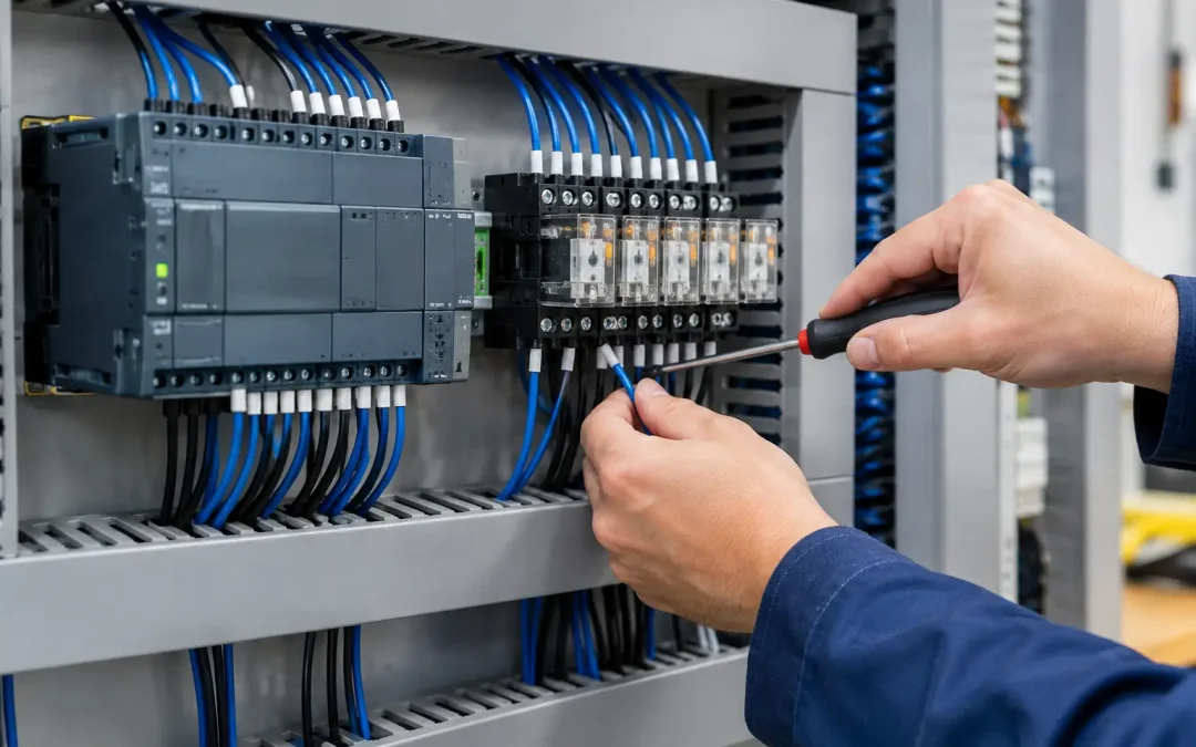
A panel can function perfectly on the bench and still be difficult to maintain on the plant floor. Interposing relays with status indicators, replaceable modules, and clear terminal markings give technicians immediate confirmation of whether the PLC command reached the interface and whether the field circuit is energized.
Terminal blocks should create logical test points between the PLC, relay, and load. This lets a technician verify output voltage, relay contact operation, and coil continuity without disturbing the controller terminals. Leave reasonable wire slack, use ferrules where appropriate, and keep wire numbers readable after installation. These details reduce the chance that a quick repair turns into a new intermittent fault.
For pneumatic manifolds, group valve outputs by zone and document the air function alongside the electrical point. A valve identified only as Output 14 is slow to diagnose. A label such as Clamp Station Extend Solenoid provides usable information under pressure. If the manifold includes common wiring or multipin connectors, document pin assignments and the protection method at the coil level.
Troubleshoot From Command to Load
When a relay-controlled device does not respond, start with the expected electrical state rather than replacing components immediately. Confirm that the PLC logic is commanding the output. Then measure the output terminal, relay coil, relay contact, and field load in sequence. This approach separates a control problem from a power problem quickly.
If the PLC output indicator turns on but the relay coil does not energize, inspect the output common, coil voltage, coil polarity, and the return path. If the relay energizes but the solenoid does not, check contact voltage under load, terminal tightness, fuse status, connector condition, and coil resistance. A voltage reading with no load can be misleading. Measure the circuit while it is commanded on, because a corroded terminal or damaged conductor may show voltage until current is required.
Intermittent faults deserve special attention. Heat, vibration, oil contamination, loose terminals, and marginal power supplies often reveal themselves only during normal machine cycling. Look for browned relay bases, pitted contacts, loose ferrules, damaged cable insulation, and coils that run unusually hot. Trend the 24 VDC supply during simultaneous valve actuation if a fault appears only when several outputs turn on together.
Match the Interface to the Application
Mechanical interposing relays remain practical for many industrial loads because they are familiar, economical, and electrically isolated. They are well suited to moderate-speed switching and applications that benefit from visible status indication and simple replacement. For rapid cycling, high-volume output banks, or applications where contact wear is unacceptable, solid-state relays or dedicated transistor output modules may be the better fit.
The selection should also reflect the pneumatic device. High-performance solenoid valves used on fast cycle equipment may need controlled suppression and fast release characteristics. Larger valve banks can require segmented power distribution to prevent voltage drop during simultaneous actuation. In demanding automation systems, the electrical interface deserves the same attention as valve flow capacity, tubing size, and air preparation.
Before changing a live circuit, apply site lockout procedures and verify absence of voltage with properly rated test equipment. Electrical work belongs to qualified personnel who understand the machine’s safety design and applicable codes.
Reliable machine control is built one intentional connection at a time. When PLC outputs, relay interfaces, coil suppression, and field power are engineered as one system, pneumatic equipment responds cleanly and the next service call becomes far easier to resolve.