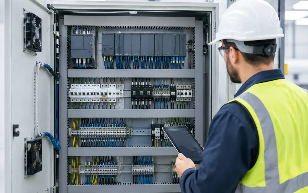
A PLC panel that works perfectly during commissioning can still become a costly service problem six months later. Heat buildup, noisy analog signals, inaccessible terminals, and unlabeled field wiring all tend to originate in one place: the PLC panel layout. For OEMs, integrators, and plant maintenance teams, a clean layout is not cosmetic. It directly affects startup time, fault isolation, expansion capacity, and long-term uptime.
The most effective layouts are planned around energy flow, signal integrity, thermal performance, and the technician who will eventually open the door at 2 a.m. That means designing beyond the minimum space needed to mount components.
Start the PLC Panel Layout With Functional Zones
A control enclosure should be organized into distinct zones rather than filled wherever open DIN rail happens to be available. Separating power distribution, control equipment, field terminations, communications hardware, and pneumatic interfaces reduces troubleshooting time and lowers the risk of electrical noise coupling into sensitive circuits.
A practical arrangement usually places incoming power and higher-voltage equipment in one area, with the PLC, low-voltage DC power supply, relays, and network components in a separate control area. Variable frequency drives, servo drives, contactors, transformers, and braking resistors deserve additional separation because they generate heat and electrical noise. Sensitive analog input modules, load-cell transmitters, and communication devices should not share a crowded wireway with motor leads.
The exact arrangement depends on enclosure size and component mix. A compact machine panel may require vertical zones, while a larger enclosure may use a top-to-bottom layout. The principle stays the same: make power paths, control paths, and field paths visually obvious.
Follow the Path of Power and Signals
A technician should be able to trace the system without guessing. Incoming AC power should move through disconnects, branch protection, distribution blocks, power supplies, and loads in a logical sequence. Low-voltage DC distribution should similarly flow from the power supply to protected circuits, PLC I/O, sensors, valves, and auxiliary devices.
Signals should have their own predictable path. Bring field wiring to terminal blocks first, then route it to I/O modules. This approach protects the PLC from repeated field-side wire changes and gives maintenance personnel a clear place to test voltage, continuity, and signal status.
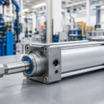
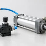
For electro-pneumatic systems, group valve manifold wiring and air-preparation monitoring signals near their associated field terminals. The pneumatic hardware may sit outside the enclosure, but its electrical connections should be labeled and organized as a functional machine subsystem, not treated as miscellaneous outputs.
Design for Heat Before Selecting the Enclosure
Thermal issues are among the most common reasons panels experience intermittent faults. PLCs, power supplies, drives, network switches, safety controllers, and solenoid interface modules all generate heat. In a crowded enclosure, that heat does not stay local. It raises the ambient temperature around every device and shortens component life.
Begin with the manufacturer heat dissipation data for each major component. Add the expected load, account for enclosure material and location, and consider the plant environment. A panel installed near a furnace, compressor room, washdown area, or direct sunlight requires a different strategy than one installed in a conditioned electrical room.
Maintain the specified clearance above and below components that rely on natural convection. Do not mount a PLC directly above a drive or power supply simply because the rail has open space. Hot air rises, so heat-producing equipment should generally be placed lower in the enclosure, with more temperature-sensitive control hardware above or in a separate compartment.
Fans, filtered vents, air conditioners, and heat exchangers can solve thermal problems, but each adds maintenance requirements. Filters clog. Fans fail. Air conditioners need appropriate sizing and service access. If a larger enclosure or better component spacing eliminates active cooling, that trade-off often delivers better long-term reliability.
Separate Noisy Power From Sensitive I/O
A well-planned PLC panel layout controls electromagnetic interference before it becomes a random fault report. Motor cables, VFD output conductors, relay coils, transformers, and switching power circuits can introduce noise into nearby analog, encoder, thermocouple, and communication wiring.
Keep AC power wiring and DC signal wiring in separate wireways whenever possible. If conductors must cross, cross them at 90 degrees rather than running them parallel. Maintain separation between drive output cables and low-level signal wiring. Use shielded cable where the application requires it, and terminate shields according to the equipment documentation and the machine grounding strategy.
Grounding cannot be an afterthought. Use a defined protective earth system with properly bonded enclosure doors, backplates, DIN rails where required, cable shields, and component grounding points. A loose or improvised ground can create both safety and noise problems. For systems with analog instrumentation, high-speed motion, or industrial Ethernet, grounding and shield termination details deserve review during design, not after commissioning.
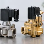
Solenoid valves deserve attention as well. Switching coils can create transients that affect nearby electronics. Select appropriate suppression methods for the valve type and control circuit, then confirm that the suppression device does not compromise required response speed. A diode can reduce voltage spikes on a DC coil, for example, but it may slow coil release in high-cycle or timing-critical applications.
Leave Room for Wiring, Service, and Expansion
A panel can look orderly with the door open and still be difficult to service if wireways are overfilled. Wire ducts need usable capacity for initial wiring, bend radius, future modifications, and troubleshooting access. As a working rule, do not design as if every duct slot and terminal position will remain untouched for the life of the machine.
Provide spare terminal blocks, spare fuse or circuit protection positions, extra DIN rail length, and reserved I/O capacity where the project economics support it. The correct amount of spare capacity depends on the machine. A fixed-purpose replacement panel may need little expansion room, while an OEM platform designed for options, conveyors, sensors, or additional valve stations benefits from a more flexible architecture.
Service access matters just as much. Install components so their terminals, indicators, fuses, and adjustment points can be reached without removing unrelated hardware. Allow adequate slack where devices may need replacement, but avoid loose loops that obstruct airflow or make wire tracing harder.
Clear, durable labeling turns this physical planning into a maintainable system. Label devices, terminal blocks, wires, disconnects, circuit protection, network ports, and pneumatic valve outputs consistently with the electrical drawings. Handwritten labels and undocumented field changes create expensive ambiguity when production is down.
Choose Components That Match the Panel Environment
The enclosure rating, internal layout, and selected components must all fit the operating environment. Dust, vibration, oil mist, washdown, ambient temperature, corrosive atmospheres, and available utility power can change the right design substantially.
For example, stainless steel enclosures and corrosion-resistant air preparation devices may be justified in food, chemical, or wet-process environments. In a high-vibration mobile or heavy-equipment application, terminal retention, wire support, and component mounting become more critical. In a production line with frequent compressed-air contamination, the electrical panel may perform correctly while pneumatic actuators and solenoids deliver inconsistent motion. The control design should account for both sides of the machine.
This is where component selection and layout meet. A properly sized PLC cannot compensate for an undersized 24 VDC power supply. A premium valve manifold will not solve erratic cylinder movement if the air supply is poorly prepared. The best panels treat electrical control, pneumatic control, and machine mechanics as one engineered system.
Review the Panel Before It Reaches the Shop Floor
Before releasing a design, review it from three perspectives: the electrical designer, the panel builder, and the maintenance technician. The designer checks ratings, protection, heat, grounding, and signal separation. The builder checks whether components can physically be installed and wired efficiently. The technician checks whether faults can be found and parts can be replaced without dismantling half the panel.
Confirm that the bill of materials matches actual mounting space, terminal counts, and wireway capacity. Verify device clearances against manufacturer requirements. Check that disconnect handles, door-mounted displays, Ethernet connections, and pneumatic interfaces have practical access. Most importantly, make sure electrical drawings reflect the panel that will actually be built.
A disciplined PLC panel layout turns a control cabinet into a serviceable production asset. When the machine stops, the value is measured in how quickly technicians can identify the fault, isolate the affected circuit, and return equipment to operation with confidence.