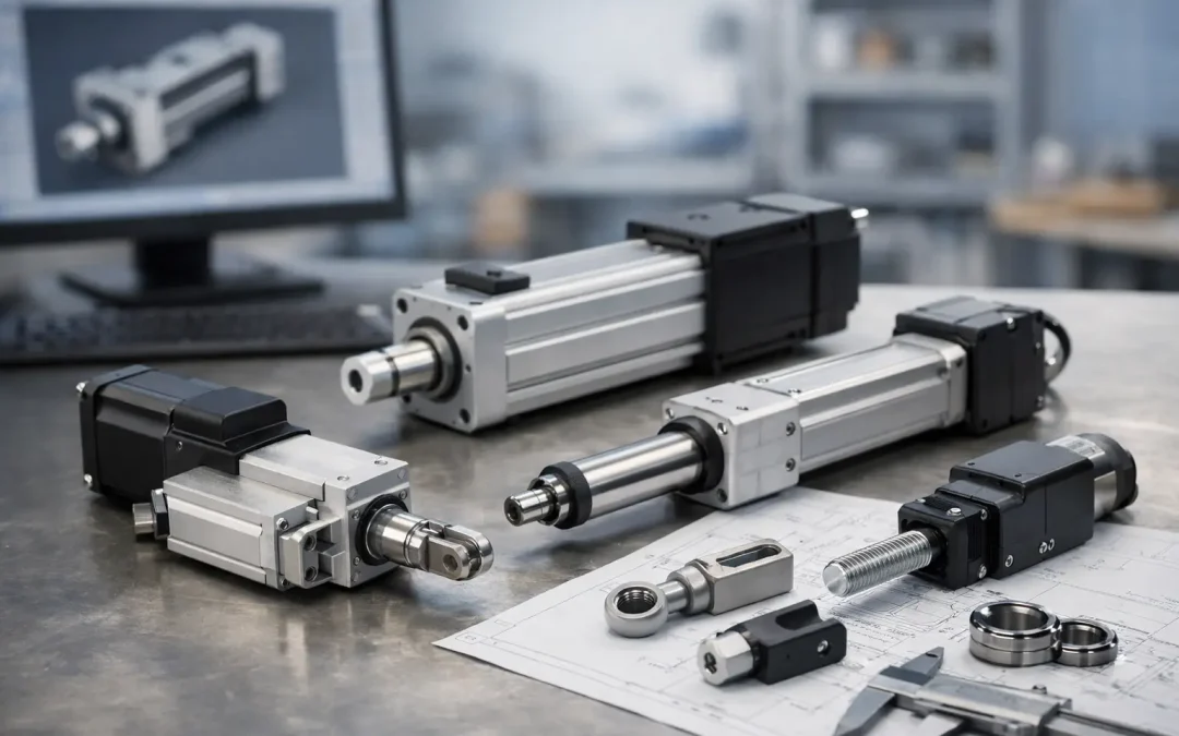
A cylinder that fits the mounting holes but misses the required stroke, speed, or end-of-travel behavior is not a successful specification. It is a future source of rework. Configured to order actuators give OEMs, integrators, and plant engineers a way to match pneumatic motion to the machine instead of redesigning the machine around a catalog part.
For demanding automation, configuration is not simply choosing bore and stroke. The actuator must work with the load, available air pressure, cycle rate, environmental exposure, sensors, controls, and installation envelope. Getting those details right before release protects uptime, shortens commissioning, and prevents a small motion problem from becoming a production problem.
Where Standard Actuators Stop Being Enough
Standard cylinders are the right answer for many applications. A basic double-acting cylinder is economical, easy to replace, and readily available when the load is predictable and the machine has room for conventional mounting. The problem begins when one or more application constraints conflict.
A packaging machine may need a compact guided slide that resists side loading during a pressing operation. A welding fixture may require a non-rotating rod, high-temperature seals, and magnetic position sensing. A food or washdown system may need stainless construction and materials selected for frequent cleaning. An assembly cell may need a custom rod end and mounting geometry to clear guarding without adding brackets that create deflection.
In those cases, selecting a standard actuator and adding accessories can appear faster at the start. It often adds hidden cost later through extra hardware, more assembly labor, longer stack-ups, air leaks at additional connections, and less predictable motion. A configured actuator package can remove those compromises at the component level.
Configured to Order Actuators Start With the Load
The first question is not which actuator series looks familiar. It is what force must be delivered at the point of work.
Cylinder force is driven by piston area and actual operating pressure, not nominal compressor pressure. Pressure drop through undersized tubing, restrictive fittings, regulators, valves, and long runs can leave an actuator with materially less force than the original calculation assumed. Friction from seals, guides, external linkages, and the load itself also consumes available force.
For a pushing or clamping operation, engineers should calculate the required force at the lowest expected line pressure, then apply a practical margin for friction and process variation. Vertical loads need separate consideration because gravity assists in one direction and opposes motion in the other. If a cylinder must accelerate a load rapidly, the peak force needed can be much higher than the static load suggests.
Bore size is therefore a performance choice, not just a dimensional choice. An oversized bore may provide useful force margin, but it also increases air consumption and can make motion harder to control. An undersized bore may function during a dry test, then stall when contamination, load variation, or pressure loss enters the system.
Side Load Changes the Actuator Choice
Rod cylinders are designed primarily for axial loading. When a moving platen, tooling arm, or workpiece creates side load or a moment load, the piston rod and internal bearings can wear prematurely. Adding an external guide system may solve the problem, but it adds alignment work and increases the footprint.
Guided cylinders and slide table actuators are often a better fit when the load must stay aligned, resist rotation, or support an offset tool. Their integrated guidance is designed to carry the moment load that would otherwise be transferred into a standard cylinder rod. The correct selection still depends on the distance from the guide to the load, acceleration, and allowable deflection.
Stroke, Speed, and Cushioning Must Work Together
Stroke is deceptively simple. The actuator needs enough travel to complete the operation, plus allowance for manufacturing variation, fixture adjustment, and sensor repeatability. Excess stroke adds cycle time and can create unnecessary impact at the end of travel. Too little stroke can cause incomplete seating, poor part release, or tolerance-related jams.
Speed requires the same discipline. High speed can improve throughput, but pneumatic systems are compressible. A load that moves smoothly at a moderate rate may bounce, overshoot, or strike the end cap when flow is increased. Long tubing runs and large valve-to-cylinder volumes can also delay response and make speed less consistent from cycle to cycle.
End-of-stroke cushioning helps manage the kinetic energy of the moving load. Adjustable pneumatic cushions are useful for many cylinder applications, but they are not a substitute for proper sizing. A heavy load moving quickly may require external shock absorbers, controlled deceleration, or a different actuator arrangement. When the process cannot tolerate impact, specify the deceleration method as part of the motion package, not as an afterthought.
Details That Belong in the Configuration
A configured actuator should reflect how the unit will be installed, controlled, and maintained. Leaving these choices until after the basic cylinder is selected creates avoidable integration work.
Mounting is one example. Front flange, rear clevis, trunnion, foot, and center mounts each transfer load differently into the machine frame. A pivoting mount is useful where the actuator travels through an arc, while rigid mounting is generally preferred for linear tooling. The mounting choice affects alignment, available space, and service access.
Rod-end configuration is equally significant. Thread type, rod extension, flats, custom adapters, and anti-rotation features determine how cleanly the actuator connects to the mechanism. When an actuator must work with an existing fixture or replacement envelope, these dimensions may be more critical than the bore size.
Magnetic pistons and position sensors should also be specified around the control requirement. Simple end-of-stroke confirmation may need two sensors. Intermediate detection, multiple positions, or setup verification may require additional sensors, adjustable brackets, or a different sensing approach. Sensor cable routing, connector style, and compatibility with the machine input system should be considered before installation, particularly where vibration, coolant, or repeated flexing is present.
For configurations with four or more application-specific requirements, document them clearly:
- Required push and pull force at minimum operating pressure
- Stroke, cycle rate, speed target, and acceptable end-of-stroke impact
- Load orientation, side load, moment load, and required guidance
- Mounting dimensions, rod-end interface, sensors, and environmental exposure
- Air quality, temperature range, chemical exposure, and washdown requirements
This information gives the technical team a usable design basis instead of a partial part number and a description of the problem after installation.
Environmental Conditions Can Override a Familiar Design
Many actuator failures are environmental failures. Standard materials may perform well in dry factory air but deteriorate in corrosive atmospheres, high heat, abrasive dust, or frequent washdown. Seal selection, rod material, body construction, lubrication approach, and sensor protection all matter.
For example, a food processing line may benefit from corrosion-resistant construction and seals suited to washdown chemicals. A high-cycle automotive fixture may prioritize wear resistance, sensor retention, and repeatable cushioning. A dusty material-handling application may need attention to rod protection and air preparation so contamination does not damage seals and valve components.
Air quality is part of the actuator specification. Water, oil carryover, and particulate contamination can shorten seal life and cause sticking or inconsistent motion. The configured actuator will only perform as intended when filtration, regulation, drainage, tubing, fittings, and valve sizing support it. Treating the cylinder as an isolated component is a common cause of intermittent pneumatic faults.
Build the Motion Package, Not Just the Cylinder
The strongest configuration decisions account for the full pneumatic circuit. Valve flow capacity influences extension and retraction speed. Tubing inside diameter and length influence pressure drop and response time. A regulator placed too far from the point of use can make force less stable during repeated cycles. Flow controls should be located and oriented to provide predictable meter-out control where appropriate.
This is especially relevant for fast automation. An actuator may be correctly sized on paper but underperform because the directional valve has insufficient flow, the exhaust path is restricted, or the machine uses small fittings throughout the circuit. Conversely, increasing air pressure to compensate for poor circuit design can raise impact, energy use, and component stress.
Factory-direct suppliers such as VidoAir can support these selections as a coordinated package: actuator, solenoid valve, air preparation, fittings, tubing, and sensing. That approach reduces compatibility questions and helps engineering teams avoid piecing together a system from components with mismatched flow, thread, voltage, or environmental ratings.
When Configuration Is Worth the Added Effort
Configured solutions are most valuable when the cost of a wrong fit exceeds the cost of engineering the correct one. That is usually true for OEM equipment, high-volume production fixtures, constrained retrofits, repeat replacement programs, and machines where downtime carries a meaningful production penalty.
For a one-off, low-speed, lightly loaded task, a standard cylinder with common accessories may remain the best commercial choice. The right answer depends on the application. Configuration earns its value when it eliminates brackets, reduces failure exposure, improves motion quality, or lets the machine meet a performance requirement that a standard unit cannot reliably meet.
Before releasing the specification, verify the real operating pressure at the actuator, the load in every direction, the available installation space, and the required behavior at both ends of travel. Those four checks catch a large share of actuator problems before they reach the floor – where every correction costs more and takes longer.