A vacuum cup that holds a clean, flat sample in a test cell can still fail on the production line. Dust, part variation, acceleration, heat, oil, and slight misalignment change the conditions at the point of contact. Knowing how to select vacuum cups means designing for those real conditions, not simply choosing the largest cup that fits the part.
For OEMs, integrators, and maintenance teams, cup selection affects more than pick reliability. It determines cycle time, compressed-air consumption, part marking, fixture complexity, and the amount of recovery margin available when incoming material changes. The right vacuum cup creates a stable seal quickly and releases cleanly. The wrong one turns a capable robot or gantry into a source of intermittent faults.
Start With the Part Surface and Handling Direction
The workpiece is the starting point. Before reviewing cup diameter, vacuum level, or mounting threads, define what the cup must contact. Surface finish, curvature, porosity, temperature, contamination, and rigidity all influence the seal.
A smooth sheet-metal panel, polished glass, or machined plastic cover generally allows a flat cup to create a fast, repeatable seal. Rough castings, textured molded parts, corrugated cartons, and wood products are different. Their irregular surfaces often require a softer sealing lip, more compliant cup geometry, or a vacuum system designed to tolerate controlled leakage.
Handling direction matters just as much. A vertical lift places the load largely perpendicular to the cup face. A horizontal transfer, part rotation, or robot wrist acceleration introduces shear forces that can make the part slide off the cup even when vertical holding force appears adequate. If the robot must accelerate aggressively, assess the peak acceleration rather than relying on the part’s static weight.
Do not overlook part stiffness. A large, thin panel can flex when lifted from one location. That flexing may break the seal at adjacent cups or leave permanent marks on a cosmetic surface. Multiple smaller cups, a distributed vacuum manifold, or a compliant mounting arrangement may provide better support than one oversized cup.
How to Select Vacuum Cups by Material
Cup material controls sealing performance, wear life, temperature capability, and the risk of contaminating the product. There is no universal best material. The correct choice depends on the part and process environment.
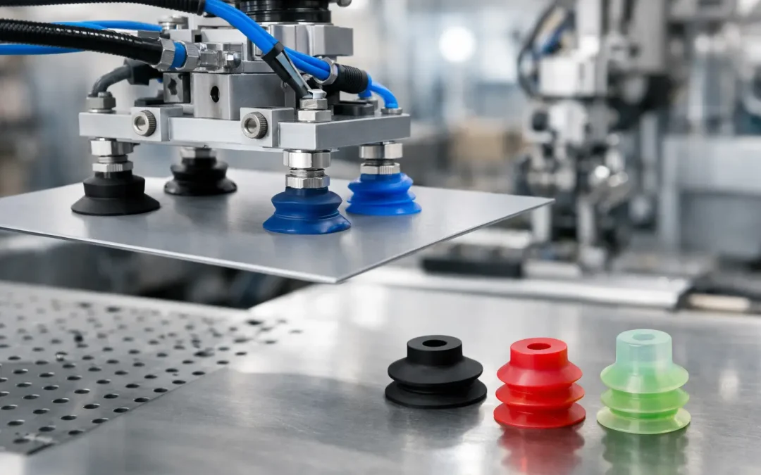
Nitrile rubber is a practical option for many industrial handling tasks, particularly where resistance to mineral oils and general shop contamination is needed. It is commonly used for metal, painted components, and machine-tending applications. However, its performance can be limited at elevated temperatures or in applications requiring food-contact compliance.
Silicone cups remain flexible across a broad temperature range and can work well on uneven surfaces, delicate materials, and hot parts. Their softer feel can improve sealing, but that softness can also reduce wear resistance in abrasive applications. Silicone may also be unsuitable where transfer of silicone residue creates downstream coating, painting, or bonding problems.
Polyurethane provides high abrasion resistance and often delivers a long service life on rough materials, cartons, textured plastics, and other demanding surfaces. It is generally less compliant than softer elastomers, so it may not be the best first choice for highly irregular or fragile parts.
For food, pharmaceutical, clean-process, or chemically demanding applications, evaluate approved elastomers and the full process exposure. Cleaning agents, washdown chemicals, oils, ultraviolet exposure, and temperature cycling can age a cup long before its visible surface appears worn. Material compatibility should be verified against the actual fluid, concentration, temperature, and exposure duration.
Match Cup Geometry to the Contact Area
Flat cups are efficient on flat, stable workpieces because they can develop holding force quickly with minimal deformation. They are a strong fit for plate stock, glass, smooth plastic panels, and machined surfaces. Their limitation is reduced ability to seal over curved or uneven areas.
Bellows cups add stroke and flexibility. A single-bellows design can compensate for moderate height variation, while multi-bellows designs provide greater compliance for uneven parts, stacking operations, and delicate products. That flexibility is valuable, but it comes with a trade-off: bellows can compress or sway under load, reducing positional precision during fast placement.
Deep cups, oval cups, and specially profiled sealing lips solve more specific problems. Oval cups can fit narrow contact zones such as rails, trim pieces, and long profiles. Deep cups can engage curved surfaces or recessed features. Cups with cleated or high-friction lips can improve grip on bags, cartons, and some textured materials, though they may leave marks on soft products.
A cup should contact a stable region of the part. Avoid seams, labels, holes, weld spatter, heavy texture changes, or areas likely to carry oil. If those areas cannot be avoided, add sensing and controls that identify a weak pick before the machine completes the transfer.
Calculate Holding Force With Real Safety Margin
Catalog holding-force values are useful, but they are usually based on controlled conditions: a clean, nonporous surface, a stated vacuum level, and force applied perpendicular to the cup. Production conditions rarely match all three.
The basic force relationship is straightforward:
`Holding force = vacuum pressure differential × effective cup area`
A larger diameter increases area and theoretical force, but it also increases the chance of interfering with part geometry and may slow evacuation if the vacuum source and line sizing are not matched. Cup force also falls when actual vacuum level drops. Long tubing runs, undersized ejectors, leaking fittings, dirty filters, and porous materials all reduce available vacuum at the cup.
Apply a safety factor that reflects the application. A clean vertical lift with controlled motion may need a moderate margin. High-speed robot motion, horizontal loading, oily surfaces, uncertain part presentation, or a potential risk to personnel calls for substantially more margin. Evaluate both the total load and the load per cup. If one cup lands imperfectly, the remaining cups may need to support the part temporarily.
For horizontal or angled handling, calculate shear separately. Friction between the cup and workpiece may be the limiting factor, not vertical holding force. More cups, a mechanical support feature, or a change in grip orientation can be more reliable than simply increasing cup diameter.
Size the Vacuum Circuit With the Cup
Vacuum cups do not operate independently from the rest of the system. A correctly specified cup can still perform poorly if the vacuum generator, valve, tubing, fittings, and filtration are undersized or poorly arranged.
Fast pick-and-place cycles require enough evacuation flow to reach the required vacuum level within the available pick window. Large cup volume, long tube lengths, and multiple cups increase the evacuation demand. A smaller cup with a short, properly sized line can outperform a larger cup connected through restrictive tubing.
Porous materials such as corrugated board, foam, rough wood, and some textiles require continuous flow because leakage is part of the process. In these cases, select a vacuum source based on flow capacity at the operating vacuum level, not only on maximum vacuum rating. A high-vacuum generator with inadequate flow may struggle to maintain grip on a leaking surface.
Include a vacuum switch where a failed pick can damage equipment, interrupt a palletizing sequence, or create a safety concern. The switch threshold should be validated under normal contamination and cycle conditions, not set from a clean bench test. For multi-cup tooling, check valves or flow restrictors can isolate a leaking cup so one imperfect contact does not collapse vacuum across the entire tool.
Account for Mounting, Alignment, and Release
Mounting hardware is often treated as an afterthought, yet it has a direct effect on cup life. A rigid mount works on consistently presented parts. A spring level compensator or ball-joint connection is often better when part height, angle, or pickup position varies. The goal is to let the cup meet the surface squarely before side loading begins.
Misalignment causes uneven lip wear and intermittent leaks. It can also pull thin parts sideways as vacuum builds. On fragile glass, films, polished finishes, and soft molded products, test for marking at full production dwell time and temperature. A cup that leaves no visible mark after one lift may still create rejects after thousands of cycles.
Release must also be designed, especially at high speed. A vacuum break valve or controlled blow-off can shorten release time, but excessive blow-off pressure can shift lightweight parts, scatter dust, or create noise. Tune the release function at the actual end-of-arm tooling position, with the actual part mass and transfer speed.
Validate the Selection on a Production-Representative Test
Bench testing is necessary, but it is not final validation. Run the proposed cup and vacuum circuit with representative parts, including known surface variation, normal contamination, and worst-case dimensional conditions. Test the highest planned acceleration, the longest reach, and the fastest cycle time.
Track vacuum level at the cup, pick confirmation timing, part movement during acceleration, release consistency, and visible cup wear. If performance changes over a shift, inspect filters, tubing, fittings, and cup condition before increasing generator size. Many apparent vacuum-capacity problems are actually leaks, contamination, or poor alignment.
VidoAir supports factory-direct vacuum components and configured pneumatic solutions for applications where standard cup selection is not enough. When the workpiece, motion profile, and vacuum circuit are evaluated together, the result is a handling system built for repeatable production rather than occasional successful picks.
The most useful final check is simple: ask what happens when the least favorable acceptable part reaches the fastest station on the line. Select the cup and vacuum system that still holds, positions, and releases that part with margin.