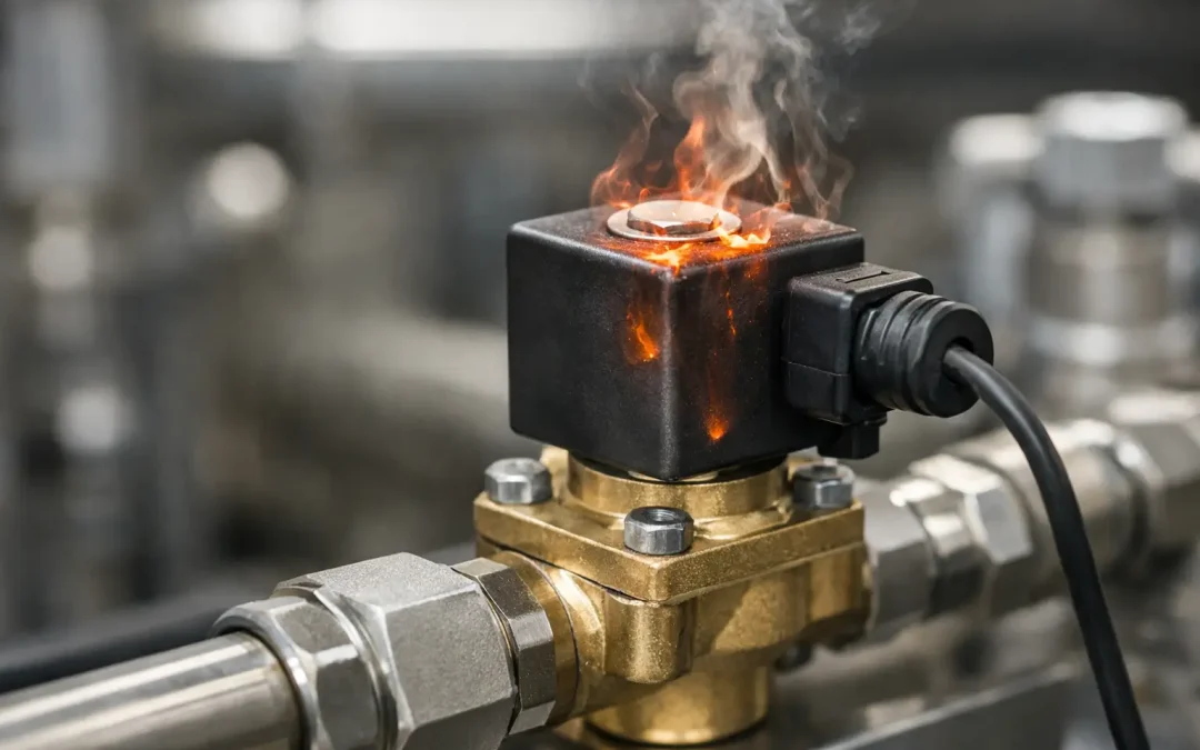
A solenoid coil that is too hot to touch can stop a production line long before it fails electrically. The challenge is that some coil heat is normal, especially on continuously energized valves. Understanding what causes solenoid valve overheating means separating normal magnetic-coil temperature rise from heat that signals a sizing, wiring, process, or mechanical problem.
For maintenance teams, the fastest path is not replacing the coil immediately. First determine whether the coil is generating excess heat, absorbing heat from the valve and process, or working harder because the internal plunger cannot move correctly. That distinction protects uptime and prevents repeat failures.
What Causes Solenoid Valve Overheating?
Solenoid valves overheat when electrical power, ambient conditions, process heat, or mechanical resistance push the coil beyond its rated thermal limits. In many cases, several factors act together. A coil installed on a hot process line, inside a poorly ventilated enclosure, and supplied with slightly excessive voltage may fail even though none of those conditions appears extreme on its own.
A coil converts electrical energy into a magnetic field, and a portion of that energy becomes heat. Manufacturers design coils to operate at a specified temperature rise under defined voltage, duty cycle, and ambient conditions. If the application falls outside those conditions, insulation can harden, crack, or short internally. The valve may then chatter, fail to shift, or burn out completely.
Incorrect Supply Voltage or Frequency
Voltage mismatch is one of the most common electrical causes. A DC coil supplied above its rated voltage draws more current and dissipates more heat. Even a modest overvoltage can materially reduce coil life in a continuously energized application.
AC coils are especially sensitive to supply conditions. An undervoltage condition may prevent the armature from pulling in fully. When the magnetic circuit remains partially open, the coil impedance is lower and current rises. The result is a loud hum, weak actuation, and rapid overheating. Supplying an AC coil with the wrong frequency can create similar problems because inductive behavior changes with frequency.
Measure voltage at the coil terminals while the valve is energized, not only at the power supply. Long cable runs, loose terminals, overloaded control circuits, and undersized conductors can create a voltage drop that is invisible during a no-load check.
A Stuck or Partially Seated Plunger
A solenoid coil is designed to run with its plunger fully seated. When contamination, corrosion, worn internal components, damaged seals, or misalignment prevent full travel, the coil may remain energized without achieving its intended magnetic condition.
On AC valves, this often produces a distinctive buzzing or chattering sound. The coil can become hot very quickly because it is continuously trying to complete the pull-in stroke. On pneumatic and fluid-control systems, contamination may come from inadequate filtration, pipe scale, compressor carryover, moisture, or media deposits. Refrigeration applications can add oil residue, moisture-related debris, and system contaminants to the diagnosis.
Do not assume the coil is the root cause simply because it is hot. Remove power, verify the valve is safe to service, and inspect the plunger, bore, spring, seals, and media path. Replacing a failed coil without correcting a sticking valve usually creates another failed coil.
Excessive Ambient or Process Temperature
A solenoid can be electrically healthy but still exceed its insulation rating because of where it is installed. Heat from ovens, compressor rooms, hydraulic power units, molding equipment, steam-adjacent piping, or direct sun exposure raises the coil’s starting temperature. A compact manifold with closely packed energized valves can produce the same effect.
Process media temperature also transfers through the valve body into the coil. This matters on hot water, oil, steam-adjacent, and refrigeration service. A standard coil may be suitable for the fluid but not for the combined fluid temperature and ambient temperature at the installation point.
Check the entire thermal stack-up: media temperature, valve-body temperature, enclosure temperature, nearby equipment, and airflow. A coil rated for a certain ambient temperature does not automatically tolerate that ambient plus a hot valve body plus heat trapped under a protective cover.
Wrong Duty Rating for the Application
Not every solenoid coil is intended for continuous energization. Intermittent-duty coils may operate reliably during short cycles but overheat when held on for minutes or hours. This issue appears after control logic changes, manual overrides are left active, or a machine spends more time in a hold state than expected.
A continuous-duty coil is usually the correct choice for a valve that remains energized during normal production. However, continuous duty does not eliminate the need to verify ambient temperature, voltage, enclosure rating, and valve operation. Duty cycle is only one part of thermal capacity.
In high-cycle applications, evaluate both on-time and switching frequency. Rapid cycling can add heat through repeated inrush current, while a valve that never gets enough off-time cannot dissipate the heat it generates.
Pressure Differential and Valve Sizing Errors
Many pilot-operated solenoid valves require a minimum pressure differential to open or stay open correctly. If the system pressure is below the valve’s operating requirement, the valve may not shift as intended. Conversely, excessive differential pressure can overload internal components and prevent reliable actuation.
The coil may remain powered while the valve fails mechanically, leading technicians to blame overheating on the electrical side. Verify the valve’s pressure range, flow direction, port configuration, media compatibility, and normally open or normally closed function. A valve selected for clean, dry compressed air may not perform the same way with vacuum, viscous fluid, contaminated water, or refrigerant service.
Direct-acting and pilot-operated designs have different operating limits. A direct-acting valve may suit low-pressure or vacuum conditions, while a pilot-operated design can provide higher flow efficiency when adequate differential pressure is available. Selecting the wrong design can create recurring heat and reliability problems.
A Practical Troubleshooting Sequence
Start with a temperature comparison rather than a touch test. Use an infrared thermometer or thermal camera to compare the suspect coil with identical valves operating under the same conditions. Remember that shiny metal surfaces can produce misleading infrared readings, so use a consistent measurement method and verify with a contact probe where practical.
Next, isolate the electrical condition. Confirm coil nameplate voltage, AC or DC designation, frequency for AC coils, wattage, and duty rating. Measure energized terminal voltage and inspect connectors, terminals, cable condition, grounding, and control output quality. A loose DIN connector or corroded terminal can cause resistance, voltage instability, and localized heating.
Then evaluate valve movement and process conditions. Listen for hum or chatter, observe response time, check for pressure at the correct ports, and confirm that exhaust or downstream flow is not restricted. For pneumatic systems, inspect the air preparation equipment. Water, oil carryover, and particulate contamination can make a normally reliable valve stick or respond slowly.
If the valve uses a removable coil, compare coil resistance against the manufacturer’s specification or against a known-good matching coil. Resistance testing is useful, but it does not prove that the plunger is moving freely under operating pressure. The best diagnosis combines electrical measurements with a mechanical and process review.
Preventing Repeat Coil Failures
Prevention begins at specification. Match coil voltage, duty cycle, insulation class, enclosure rating, and temperature limits to the actual machine environment. Specify valve materials and seals for the media, pressure, and temperature range rather than selecting solely by port size or initial cost.
For pneumatic automation, clean and properly conditioned air remains one of the most effective reliability controls. Use filtration appropriate to the valve and actuator requirements, maintain drains, and address compressor oil carryover before it reaches precision control components. For fluid and refrigeration systems, keep contaminants and moisture within the limits required by the valve design.
Installation details matter as well. Leave clearance around coils where possible, avoid mounting directly beside high-radiant-heat equipment, and do not bury energized valves inside enclosures without considering heat dissipation. When multiple solenoids are mounted on a manifold, review their simultaneous-on condition instead of assuming each valve’s individual rating applies to the full assembly.
For demanding OEM and retrofit applications, VidoAir can help match high-performance solenoids, pneumatic controls, air preparation components, and configured hardware to the operating conditions that drive coil life. The right component is not simply the one that fits the port. It is the one that can hold its electrical, mechanical, and thermal margin through real production cycles.
A hot coil deserves attention, but it also provides useful evidence. Treat its temperature as a system-level diagnostic signal, then verify voltage, duty, valve motion, pressure conditions, contamination control, and surrounding heat before putting the machine back into service.