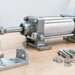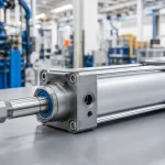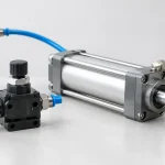
A cylinder that hesitates at the end of a stroke, an actuator that will not hold position after a stop command, or a machine that loses cycles only during peak production often points back to one control point: the valve. This pneumatic directional valve review focuses on how experienced engineers and technicians should evaluate directional valves for real production equipment, where flow capacity, switching behavior, contamination tolerance, and service access matter more than a favorable catalog price.
A directional valve is rarely the most expensive component in a pneumatic circuit. It can, however, determine whether the circuit delivers repeatable motion or becomes a recurring maintenance issue. The right choice begins with the application load and motion profile, not simply with port size or the number of positions shown in a valve symbol.
What a Pneumatic Directional Valve Review Should Measure
A useful valve review starts with the job the valve must perform. A 5/2 solenoid valve operating a double-acting cylinder on a high-speed packaging line has different priorities than a 3/2 valve piloting a process actuator or a manually operated valve used at a maintenance station. The circuit symbol establishes the function, but it does not establish the full performance requirement.
For most OEM and retrofit decisions, evaluate the valve across four operating factors: required flow, response consistency, environmental exposure, and maintenance impact. These factors are connected. A valve selected with insufficient effective flow area can slow a cylinder, increase pressure drop, and create inconsistent cycle timing. A valve with acceptable flow but poor contamination control can perform well during commissioning and degrade after months on the line.
Flow Rating Is Not the Same as Port Size
Port threads help define mechanical compatibility. They do not prove that a valve can move enough air for the required cylinder speed. Compare the manufacturer flow rating, effective flow area, operating pressure range, and the restriction created by fittings, tubing, silencers, and downstream flow controls.
This matters especially when a system is upgraded. Replacing a 1/4-inch valve with another 1/4-inch valve may appear straightforward, yet the replacement may have a materially different flow path. If the original application is already near its cycle-time limit, that difference can be enough to cause a missed sensor window or reduce output.
A practical check is to observe cylinder behavior at normal production pressure, not only at an unloaded test pressure. Watch extension and retraction under actual payload, then review pressure at the valve inlet and cylinder ports during motion. A large pressure drop at the valve or undersized supply plumbing calls for a flow-path correction, not a faster cylinder adjustment.
Spool, Poppet, and Pilot Design Change the Trade-Offs
Spool valves are widely used because they support compact multi-port directional control and manifold mounting. They are well suited to automated machinery that needs organized valve banks, electrical control, and straightforward replacement. Their performance depends on precise internal clearances and clean, properly prepared compressed air.
Poppet-style designs can offer fast switching and low leakage in certain configurations, but their physical size and available functions may not fit every manifold-based machine design. The preferred construction depends on the circuit, the environment, and what failure mode is least acceptable.
Pilot-operated directional valves can provide higher flow with a smaller solenoid, but they require sufficient pilot pressure and proper exhaust conditions. A common field mistake is assuming that a pilot-operated valve will shift correctly at every low-pressure operating point. If supply pressure falls below the pilot requirement, the valve may fail to shift fully, shift slowly, or behave inconsistently. For vacuum, low-pressure, or variable-pressure circuits, confirm the pilot arrangement before specifying the valve.
Electrical Control Must Match the Machine
A valve coil should be reviewed as an electrical device, not treated as an interchangeable accessory. Confirm the voltage, AC or DC supply, connector style, power consumption, duty cycle, ingress protection, and whether the control system can supply the necessary inrush or holding current. A 24 VDC coil is common in industrial automation, but common does not mean universal.
Heat deserves particular attention in dense manifolds. Multiple energized coils in an enclosed panel or warm machine enclosure can elevate coil temperature beyond what a single-valve bench test suggests. Continuous-duty applications need a coil and valve body designed for sustained operation at the actual ambient temperature.
For high-cycle equipment, response time should also be considered as a system value. Published switching time is helpful, but total actuator response includes PLC output timing, wire length, coil energization, pilot fill time, tubing volume, and cylinder load. When diagnosing a slow machine, replacing the valve without checking the rest of that chain can waste both time and budget.
Leakage, Center Position, and Safe Machine Behavior
Valve leakage affects both energy use and motion control. Internal leakage may be tolerable in a noncritical blow-off circuit but unacceptable when a vertical load must remain stationary during a pause. External leakage creates additional concerns, including lost compressor capacity, noise, and contamination in sensitive production areas.
The center condition of a 5/3 valve requires equally careful review. Center closed, center exhaust, and center pressure configurations produce very different machine behavior when the solenoids are de-energized. There is no universally correct center position.
Center closed can help trap air and hold a cylinder temporarily, although internal leakage, hose expansion, and load changes still affect position. Center exhaust can release actuator pressure for a safer stopped condition, but it may allow a load to move unless separate mechanical safeguards are present. Center pressure may support a particular operating sequence, yet it can keep force applied when operators expect the machine to be inactive. Review the machine risk assessment and fault-state requirements before treating center position as a standard selection field.
Contamination Resistance Is a System Decision
Many directional-valve failures begin upstream. Water, oil carryover, pipe scale, thread sealant debris, and damaged tubing can prevent a spool from moving freely or compromise internal seals. Replacing the valve may restore operation temporarily, but the replacement will face the same contamination unless the air-preparation issue is corrected.
A properly selected filter, regulator, drain strategy, and appropriate lubricant policy protect valve performance. Some valves are designed for non-lubricated service, while others may have material or service requirements that need specific attention. Do not add lubricators as a universal fix. Once lubrication is introduced into certain circuits, it may need to be maintained consistently, and it can create compatibility issues with downstream processes.
For washdown, dusty operations, outdoor equipment, and corrosion-prone environments, review body material, seals, coil enclosure, exhaust protection, and mounting orientation. Exhaust ports can draw in contaminants during pressure changes if they are left exposed. Mufflers or protected exhaust fittings may be a small addition that prevents a larger reliability problem.
Manifold Systems Versus Individual Valves
Individual inline or body-ported valves make sense for simple circuits, field repairs, and equipment where valves are distributed across the machine. They can also simplify access when each actuator has a dedicated local control point.
Manifolds are often the stronger choice for machines with multiple actuators. They reduce tubing runs, centralize electrical connections, improve cabinet or machine-frame organization, and make it easier to expand a station. The trade-off is that a manifold requires disciplined planning for common supply, exhaust capacity, electrical addressing, spare positions, and service clearance.
A well-designed manifold should not create a single difficult-to-repair point. Specify clear valve identification, accessible connectors, isolation where needed, and a replacement strategy that allows technicians to restore a station quickly. VidoAir supports both standard pneumatic control components and configured solutions for applications where porting, coil specifications, and available space cannot be treated as afterthoughts.
Field Checks Before You Replace a Valve
When a directional valve is suspected, verify the fault before ordering a replacement. Confirm that the coil receives the correct voltage under load. Check whether manual override shifts the valve, while following machine safety procedures. Inspect exhaust restrictions, supply pressure, damaged tubing, and cylinder binding.
If the valve shifts electrically but the actuator remains slow, measure pressure at the valve and near the cylinder during the affected stroke. If the coil is energized but the spool does not move, contamination, pilot-pressure loss, mechanical damage, or a failed coil may be involved. A valve replacement is justified when the evidence supports it, not because it is the most visible component in the circuit.
Document the original valve function, port size, voltage, flow requirement, mounting pattern, and fault condition before selecting a substitute. This record prevents a common replacement error: installing a valve that fits the threads and connector but changes the machine’s fail-state behavior.
The strongest directional-valve selection is the one that gives maintenance a clear diagnostic path, gives engineering predictable motion, and gives production one less reason to stop the line.