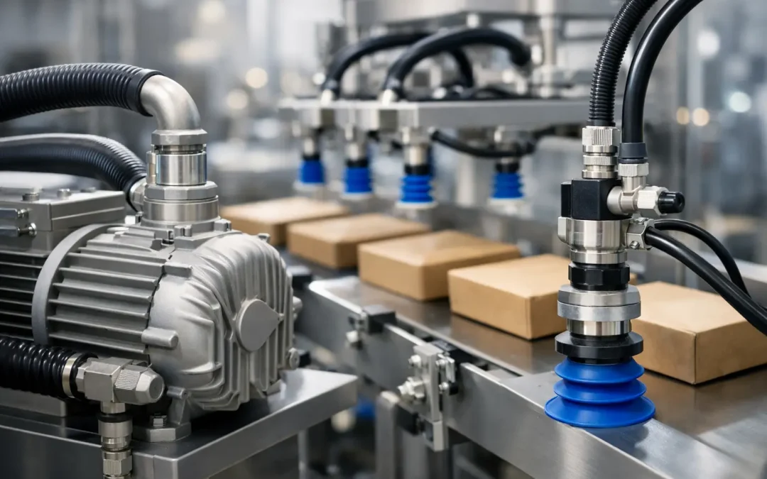
A cartoner that misses one blank, a bagging machine that drops a pouch, or a case packer that loses a layer can turn a small vacuum issue into lost output quickly. The top vacuum components for packaging lines are not simply the parts that create the highest vacuum level. They are the components that maintain stable pickup, release cleanly, tolerate contamination, and recover fast enough to support the machine’s real cycle rate.
For engineers and maintenance teams, selection starts with the material being handled and ends with measured performance at the point of use. A vacuum system that performs well on dry corrugated blanks may fail when humidity increases, carton dust accumulates, or the line changes to a coated film package. The right component set must account for those operating conditions rather than relying on a single catalog specification.
Top Vacuum Components for Packaging Lines
A high-performance packaging vacuum circuit is usually built around six connected functions: vacuum generation, gripping, switching, filtration, vacuum monitoring, and controlled release. Each affects the others. Increasing generator capacity, for example, will not correct a leaking cup manifold or a restrictive filter placed too close to the source.
Vacuum generators sized for flow, not just vacuum level
Pneumatic vacuum generators, often called ejectors or Venturi generators, remain a practical choice for packaging machinery because they are compact, fast acting, and easy to place near the load. Their performance depends on compressed-air pressure, nozzle design, and the relationship between available vacuum flow and leakage in the application.
The common specification mistake is selecting a generator only by its maximum vacuum rating. High vacuum can be useful for dense, nonporous materials, but flow capacity often matters more on corrugated, textured paperboard, woven bags, or products with imperfect sealing surfaces. Those materials leak continuously. A generator must remove incoming air fast enough to preserve holding force at the cup.
Centralized vacuum can be the better approach for large case packers or multi-station lines with relatively steady demand. It can reduce compressed-air consumption and make maintenance more centralized. The trade-off is longer vacuum paths, larger line volumes, and potentially slower response unless local valves and properly sized reservoirs are used. For fast pick-and-place stations, decentralized ejectors mounted near the cups often deliver more predictable response.
Vacuum cups matched to product surface and motion
The cup is where vacuum performance meets the package. Cup diameter, lip geometry, material hardness, stroke, and mounting compliance all influence whether a product is gripped reliably without damage.
Flat cups suit smooth cartons, labels, rigid trays, and sheet products when the pickup surface is consistent. Bellows cups provide added compensation for uneven carton surfaces, variable stack heights, and minor misalignment. Oval cups can provide more holding area where a round cup will not fit, especially on narrow carton panels or pouches. For flexible film packaging, a softer lip may conform better, but it can also wear more quickly in abrasive or high-cycle applications.
Cup size should be based on holding force with a safety factor that reflects acceleration, orientation, and product variation. A light carton moving vertically at modest speed needs far less force than a filled pouch transferred at high acceleration with a rotating end effector. Larger cups add holding force, but they also increase internal volume and can slow evacuation. More cups are not always the answer if they create too much leak path when one cup lands on a gap or edge.
For food, pharmaceutical, and washdown packaging environments, material compatibility matters as much as geometry. Specify cup materials that tolerate cleaning agents, temperature exposure, oil, and the product-contact requirements of the machine. A cup that swells, hardens, or sheds material creates both uptime and quality problems.
Fast vacuum valves and controlled blow-off
A vacuum valve determines when the cup sees vacuum. In high-speed packaging, valve response time directly affects cycle time and placement accuracy. Mounting the valve close to the cup manifold minimizes the air volume that must be evacuated and vented on every cycle.
Release deserves the same attention as pickup. A controlled blow-off pulse breaks the vacuum quickly so cartons, labels, or flexible pouches do not cling to the cup during transfer. Excessive blow-off pressure, however, can distort lightweight material, scatter dust, or push a package out of position. Use only enough positive pressure to deliver consistent release, then verify the result at normal production speed.
Valves with integrated blow-off control can simplify tubing and reduce assembly points. Separate valves may offer more flexibility for complex tooling where groups of cups require different timing. The best arrangement depends on the number of zones, package variation, and how often the machine changes formats.
Filters that protect performance without restricting flow
Packaging lines generate contamination: corrugated dust, paper fibers, film trim, powder residue, and occasional product debris. Without filtration, contaminants can enter ejector nozzles, valves, sensors, and silencers. The result is gradual performance loss that often appears as an intermittent pickup fault.
Install vacuum filters where they protect sensitive components while remaining accessible for service. A filter located near the cup circuit can stop debris before it enters the manifold, but it must have sufficient flow capacity. An undersized element creates a pressure drop that reduces pickup speed and may lead technicians to increase supply pressure unnecessarily.
Filter service intervals should be based on actual condition and measured system performance, not only a calendar. A clean-room film operation and a dusty corrugated case-packing cell have very different maintenance needs. If vacuum level at the cup trends downward while compressed-air supply remains stable, inspect filters, silencers, and cup wear before replacing the generator.
Vacuum switches and sensors for proof of pickup
A machine should not assume that a vacuum command equals a successful pickup. Vacuum switches and electronic sensors provide the confirmation needed to prevent empty picks, dropped products, and downstream jams.
For a simple carton pickup, a vacuum switch can signal that a minimum threshold has been reached before the axis moves. On more demanding systems, an analog vacuum sensor provides trend data that can reveal leaks, damaged cups, or deteriorating material before failures become frequent. This is especially useful on robotic end effectors, where a single failed cup can affect load stability.
Set thresholds with real production material, including the least favorable package condition. A switch set too close to the normal operating level can chatter as material porosity changes. A threshold set too low may confirm a partial pickup that is not secure enough for the next move. Add suitable delay logic only when needed; excessive timing delays can hide a weak circuit and cost cycle time.
Check valves, reservoirs, tubing, and fittings
These supporting parts often decide whether a vacuum circuit remains stable during production. Check valves isolate individual cups or vacuum zones. If one cup lands on a carton cutout or misses the product entirely, a check valve can limit the leak so the remaining cups retain holding force.
Small vacuum reservoirs can provide a short-term buffer during rapid demand changes or brief supply fluctuations. They are useful when a centralized source feeds a fast local station. Yet a reservoir that is too large increases evacuation time and may delay release, so it should be sized around the actual volume and cycle profile.
Tubing must have enough inside diameter to support required flow without excessive restriction. Long, narrow tubing is a frequent cause of slow pickup. Keep runs short, avoid unnecessary elbows, and use fittings designed to maintain a reliable seal under vacuum. A fitting that appears acceptable under positive pressure can admit air under vacuum and create a fault that is difficult to trace.
A Better Way to Specify Vacuum Components
Start with the package, not the existing bill of materials. Document package weight, surface type, porosity, available pickup area, temperature, contamination exposure, travel direction, acceleration, and target cycle time. Then measure vacuum at the cup during the most demanding point of the machine cycle.
This approach separates three common problems that are often treated as one. Low vacuum level can indicate inadequate source capacity or a restriction. Slow vacuum buildup usually points to line volume, tubing diameter, valve location, or leakage. Unstable vacuum after pickup often suggests cup sealing, product variation, or an unisolated open cup.
When a line handles multiple package formats, consider zoned tooling with independently controlled cup groups. This allows operators to activate only the cups needed for each format and reduces leakage from unused cups. It also makes changeover settings more repeatable than manually plugging lines or accepting inconsistent pickup performance.
Factory-direct sourcing can simplify this work when standard vacuum components and configured assemblies are available from the same technical resource. VidoAir supports packaging equipment builders and maintenance teams with vacuum hardware selected for demanding pneumatic automation applications, helping reduce the gaps between specification, replacement, and production support.
The strongest packaging vacuum systems are not oversized by default. They are measured at the cup, protected from contamination, designed for controlled release, and monitored for the early signs of loss. That gives maintenance teams a clear path to correct the cause before the next missed pick becomes a stopped line.