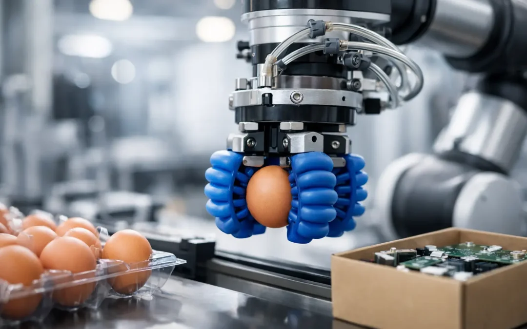
A soft gripper can solve a difficult picking problem in minutes, then create an intermittent production fault if the air circuit, end-of-arm tooling, or control logic is treated as an afterthought. This soft robotic gripper integration guide focuses on the details that determine whether a gripper delivers repeatable cycle times and gentle handling on the production floor.
Soft grippers are especially effective where conventional parallel jaws damage products, need frequent changeover, or cannot tolerate part variation. Food products, cosmetics, bags, irregular castings, delicate assemblies, and loosely positioned components are common candidates. Their compliance is a major advantage, but it also means gripping force is less direct and more sensitive to pressure, finger geometry, motion profile, and part presentation.
Start With the Actual Handling Window
Do not select a soft gripper from payload alone. The relevant question is whether the gripper can retain the part through the full motion cycle, including acceleration, deceleration, wrist rotation, and any unexpected variation in product position.
Begin by documenting part weight, surface condition, temperature, allowable contact area, and dimensional variation. A dry, rigid carton and a lightly oily stamped component with the same weight demand very different gripping strategies. For food or consumer goods, also consider whether the part can deform under pressure and whether contact materials must meet plant sanitation requirements.
Calculate the required holding force with a safety factor that reflects the process. A slow pick-and-place application may need a modest margin. A high-speed delta robot, vertical lift, or abrupt 90-degree rotation needs more allowance because inertial loads can exceed the part’s static weight. The gripper manufacturer should provide force data by supply pressure and finger configuration, but validate it with the real product whenever possible.
Part orientation matters as much as force. A soft gripper holding a product from the side relies on friction. A downward-facing grip may benefit from mechanical geometry, such as fingers wrapping below a flange or shoulder. If the application depends only on friction, minor contamination or a pressure drop can quickly become a dropped-part problem.
Soft Robotic Gripper Integration Guide: Size the Air System
Pneumatic supply quality determines gripper consistency. Soft actuators consume relatively small volumes per cycle, yet they are often installed at the far end of a robot arm, downstream from restrictive tubing, compact fittings, and shared valves. The result can be pressure lag at the gripper even when the main header gauge appears stable.
Size tubing and valves for the required response time, not just nominal port size. Long, narrow tubing adds flow restriction and makes grip and release timing less predictable. Place the valve as close to the gripper as the robot architecture allows. For a moving robot arm, use flexible pneumatic tubing with appropriate bend radius and abrasion protection, then secure it so it cannot snag, pinch, or fatigue at repeated motion points.
A typical circuit includes filtered, regulated air, an electrically controlled solenoid valve, tubing, fittings, and the gripper. Depending on the application, it may also require a pressure sensor, flow controls, a soft-start function, or a small local reservoir. Each component has a purpose:
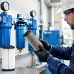
- Filtration protects valves and gripper passages from moisture, compressor debris, and oil contamination.
- A dedicated regulator sets the maximum gripping pressure and prevents an upstream line-pressure change from altering product handling.
- A pressure sensor confirms that commanded grip pressure was actually achieved.
- Meter-out flow control can reduce finger snap and product impact, while meter-in control may be preferable where fast release is critical.
- Exhaust silencing reduces noise, but an undersized silencer can slow release and extend the robot cycle.
Use a regulator with sufficient flow capacity and stable adjustment resolution. If the process handles fragile products, a low-pressure regulator with accurate control in the operating range is more useful than a general-purpose unit set near its minimum. Record the pressure setpoint in the machine recipe or setup documentation. A technician should not have to guess whether a gripper was intended to run at 20 psi or 45 psi.
Build Controls Around Verification, Not Assumption
A PLC output that energizes a solenoid is not proof that the part is secured. For low-risk applications, a timed dwell after the grip command may be adequate. For high-value products, automated assembly, or unattended operation, add feedback that can distinguish a completed grip from a failed one.
Pressure feedback is the most direct pneumatic signal. The control program can issue a close command, wait for pressure to reach a defined threshold, then permit robot travel. It should also alarm when pressure does not build within the allowed time. This catches disconnected tubing, clogged fittings, failed valves, and major leaks before a part is carried across the cell.
Pressure alone does not confirm part presence. A gripper can reach pressure while closing on empty space. When missed picks are costly, combine pressure monitoring with a vision check, vacuum confirmation, part sensor, robot torque monitoring, or downstream inspection. The correct method depends on cycle time, product variability, and the consequences of a bad pick.
Use clear fault logic. A pressure fault should stop motion safely, identify the affected station, and preserve enough diagnostic information for maintenance to act. Avoid programming repeated close-open retries without limits. A retry can recover from a minor presentation error, but repeated attempts can damage products or conceal a deteriorating air supply issue.
Design the End-of-Arm Tooling for Service
The gripper should not be the only component considered on the robot flange. Adapter plates, cable routing, pneumatic connections, and fastener access all affect uptime. Keep the assembly compact to reduce wrist inertia, but leave room to inspect fittings and replace wear items without removing the full tool.
Check the robot’s allowable payload and moment of inertia with the complete end effector installed. Include the gripper, mounting plate, valves, sensors, fittings, hoses, and any protective guards. A lightweight soft gripper can still become a high-inertia tool when mounted on a long bracket or supplied by an oversized manifold.
Finger alignment deserves particular attention. If fingers contact the part unevenly, the gripper may twist the product, create inconsistent holding force, or wear one side faster. Use hard stops or locating features in the fixture where product presentation is inconsistent. Compliance improves tolerance to variation, but it cannot compensate for a part arriving outside the robot’s usable pick window.
For washdown, dusty, hot, or corrosive environments, specify materials and protection at the system level. Stainless steel air preparation devices, suitable fittings, protected valve enclosures, and compatible tubing may be necessary. Chemical compatibility is not limited to the gripper body. Cleaning agents can affect tubing, seals, and sensor housings as well.
Troubleshoot the Failures That Affect Cycle Time
Slow gripping usually starts with restricted flow, not a failed gripper. Check regulator capacity, valve flow rating, tubing length, tubing inside diameter, exhaust restriction, and contamination in filters or fittings. Compare pressure at the regulator with pressure measured near the gripper during an actual cycle. A large dynamic pressure drop points to a flow problem.
Inconsistent grip force often comes from unstable supply pressure, regulator creep, leaks, or product variation. Inspect fittings with the circuit pressurized, confirm that the regulator holds its setpoint, and review whether another machine function shares the same undersized air branch. If the product is variable, the answer may be a revised finger configuration or a pressure recipe tied to product type rather than simply increasing pressure.
Dropped parts during robot acceleration are commonly caused by a static-only force calculation. Review robot speed, acceleration, orientation changes, and the path after pick. Reducing acceleration may solve the issue, but a better fix can be improved mechanical engagement, a different gripper size, or a revised approach angle that lets the fingers wrap around a more secure part feature.
Premature finger wear often points to misalignment, excessive pressure, sharp product edges, or improper contact during fixture entry. A soft gripper should deform around the product, not scrape repeatedly across guides, nests, or adjacent hardware. Adjust the robot path and verify that the gripper clears fixtures through the entire motion envelope.
Validate With Production Conditions
Bench testing is necessary, but it is not qualification. Run the intended product range at normal production speed, include worst-case weight and surface conditions, and test after the pneumatic system has been operating long enough to reveal pressure fluctuations. Log failed picks, pressure build time, release time, and product damage rather than relying only on operator observation.
Before release, establish acceptance limits for grip pressure, cycle timing, allowable leak rate, and replacement intervals for consumable components. Keep a spare set of critical fittings, valves, and soft gripping elements where the process cannot tolerate extended downtime. Factory-direct component availability matters most when a small pneumatic issue threatens a larger production schedule.
A properly integrated soft gripper is not merely a gentler end effector. It is a controlled handling system where air quality, flow capacity, feedback, tooling geometry, and robot motion all support the same result: reliable picks that protect the product and keep the cell moving.