A pneumatic system can have adequate compressor capacity, correctly sized valves, and premium actuators yet still perform poorly because the regulator was selected by port size alone. Pressure drift, slow cylinder motion, inconsistent clamp force, and excessive air consumption often start at the point where supply pressure is reduced and controlled. Knowing how to specify air regulators means matching the regulator to real flow demand, pressure behavior, environmental exposure, and the consequences of failure.
For OEMs, integrators, and maintenance teams, the right specification is not simply a matter of selecting a 1/4-inch or 1/2-inch unit. The regulator must maintain usable downstream pressure while air demand changes, survive the plant environment, and fit the service strategy of the machine. That requires looking beyond the nominal adjustment range printed in a catalog.
Start With Required Downstream Pressure
Begin with the pressure the application actually needs at the point of use. This is not always the same as the pressure measured immediately downstream of the regulator. Long tubing runs, restrictive fittings, directional valves, silencers, and quick exhaust devices can all create pressure loss before air reaches the actuator.
Determine the minimum pressure required for the load under worst-case conditions. For a cylinder, this starts with force: cylinder force equals effective piston area multiplied by available pressure. Account for friction, side loading, seal breakaway force, tooling weight, and a practical operating margin. A vertical actuator or a gripper handling variable parts may need substantially more margin than a lightly loaded horizontal pusher.
Then establish the normal set pressure. A regulator should control at a pressure high enough to deliver required force but not so high that the machine wastes compressed air, increases impact energy, or shortens actuator life. Running every branch at plant header pressure is common, but it is rarely efficient. Separate pressure zones often improve motion consistency and reduce consumption.
Supply pressure also matters. If a plant header normally runs at 100 psi but periodically falls to 80 psi during peak demand, a regulator set at 75 psi has little control headroom. Select a design that can deliver the needed regulated pressure throughout the expected inlet-pressure range.
Size the Regulator for Dynamic Flow, Not Port Threads
Port size is a connection detail, not a flow calculation. A regulator with matching threads may still be too restrictive when multiple cylinders cycle together, when an air blowoff circuit opens, or when an actuator must move quickly at the end of a machine cycle.
Use the highest expected simultaneous demand rather than the average air consumption. Consider every device downstream of that regulator: cylinders, rotary actuators, grippers, air pilots, vacuum generators, purge circuits, and blow guns. A packaging machine may appear modest at idle, then demand a sharp burst of air when several axes extend at once.
The key performance measure is pressure drop, often called droop. Droop is the reduction in outlet pressure as downstream flow rises. A regulator may hold its setpoint with no flow, then fall several psi during an actuator stroke. If the application depends on repeatable clamp force or tightly controlled cylinder speed, that drop can create quality problems.
Review the manufacturer flow curve at the intended inlet pressure and regulated outlet pressure. Do not compare only maximum advertised flow ratings, because those values may be stated under different pressure conditions or at a pressure drop that is unacceptable for the application. Select a regulator that supplies peak flow while keeping downstream pressure above the minimum required level.
Oversizing also has limits. An excessively large regulator can make fine low-flow adjustment less precise and adds unnecessary cost and package size. The best selection has enough flow margin for simultaneous events without sacrificing stable control in the normal operating range.
Account for Air Line Volume and Response
Large downstream volumes change the way a regulator behaves. Long tubing, manifold cavities, reservoirs, and multiple cylinders create a stored-air volume that takes time to fill and vent. A regulator that is adequately sized for steady flow may still be slow to recover after repeated high-demand cycles.
For fast automation, evaluate recovery behavior during the actual machine sequence. If pressure falls during a rapid series of strokes, increasing regulator capacity may help, but so may reducing restrictions upstream, using larger distribution tubing, or dividing the circuit into separate regulated zones. A local receiver can support short demand peaks, provided it does not conceal a chronic undersupply problem.
Choose Control Characteristics for the Process
Most industrial air regulators are relieving. When the setpoint is lowered, excess downstream pressure can vent through the regulator. This is useful where pressure must be reduced quickly and safely, such as an adjustable clamping circuit or a test fixture.
A non-relieving regulator does not vent downstream pressure when the adjustment is reduced. It is appropriate where vented air is undesirable, where downstream media must be contained, or where the circuit design requires pressure to remain until a separate exhaust path opens. The trade-off is that the outlet may remain above the new setting until air is consumed or intentionally released.
For applications requiring close pressure control, look at sensitivity, repeatability, hysteresis, and gauge resolution. A general-purpose mechanical regulator is effective for many cylinders and air tools, but it may not be the right answer for proportional force control, precision tensioning, low-pressure dispensing, or electronically controlled recipes.
Electro-pneumatic regulators provide an electrical command signal and can adjust pressure automatically as machine conditions change. They add cost, wiring, and control integration, but they can eliminate manual adjustment errors and enable multiple stored pressure settings. On a flexible production line, that capability can be more valuable than the initial component savings of a manual regulator.
Specify the Correct Pressure Range and Adjustment Method
Avoid specifying a broad pressure range simply because it appears more versatile. A regulator designed for 0 to 125 psi may be less controllable in a process that normally runs between 5 and 15 psi. Choose the narrowest practical adjustment range for the operating setpoint, particularly when low-pressure accuracy affects product quality or actuator force.
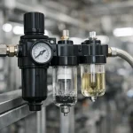
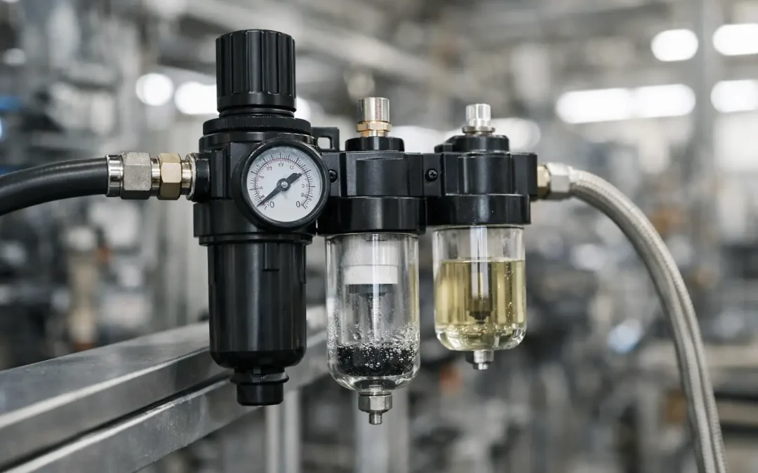
The adjustment mechanism should match access and change-control requirements. A knob is practical for maintenance settings and local troubleshooting. A locking knob or tamper-resistant adjustment is better where unauthorized changes could affect safety, quality, or energy use. Panel-mounted regulators can place adjustment and indication outside an enclosure, while modular air-preparation assemblies keep filters, regulators, lubricators, and shutoff devices compact at the machine inlet.
Specify a gauge when technicians need fast local verification. For difficult-to-access installations or control systems that require recorded data, use a pressure transducer instead of relying only on a mechanical gauge. Keep in mind that a gauge at the regulator does not prove pressure at the actuator during flow. Critical applications may need sensing closer to the point of use.
Match Materials and Construction to the Environment
Standard aluminum-bodied regulators with common elastomer seals perform well in clean, dry industrial air. Demanding environments require a more deliberate material selection. Washdown areas, food and beverage equipment, corrosive chemical exposure, outdoor machinery, and offshore installations may call for stainless steel construction, compatible seals, protected gauges, and fittings that resist corrosion.
Temperature matters as much as moisture. Verify the allowable operating temperature for the regulator, bowl, seals, gauge, and any electronic components. Cold environments can increase seal stiffness and create freezing risk if water reaches the air system. Hot enclosures can shorten elastomer life and affect electronic accuracy.
Air quality should be addressed upstream of the regulator. Water, compressor oil carryover, rust, and particulates can cause sticking, leakage, and unstable control. A properly selected filter protects the regulator, but the filter element must match the contamination risk and be maintained. In severe service, use a staged air-preparation strategy rather than expecting one small filter-regulator to solve every air-quality issue.
Build Serviceability Into the Specification
A regulator is a small component with a direct effect on uptime. Specify it so technicians can inspect the gauge, drain upstream filtration, adjust the setting, and replace wear items without removing surrounding equipment. Confirm clearance for bowls, adjustment knobs, and fittings before finalizing the layout.
Standardizing mounting patterns, port sizes, gauge connections, and spare configurations across similar machines reduces maintenance variation. It also prevents a replacement from being chosen solely because it physically fits. VidoAir can support standard and configured air-preparation assemblies when the application needs a specific combination of filtration, regulated pressure, mounting, and environmental resistance.
Before releasing the design, validate the regulator under the machine’s highest-demand cycle, lowest expected inlet pressure, and normal operating temperature. Watch downstream pressure during motion, not just at idle. The specification is complete when the machine still delivers the required force, speed, and repeatability under the conditions that production will actually impose.