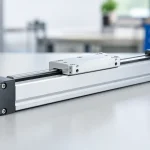
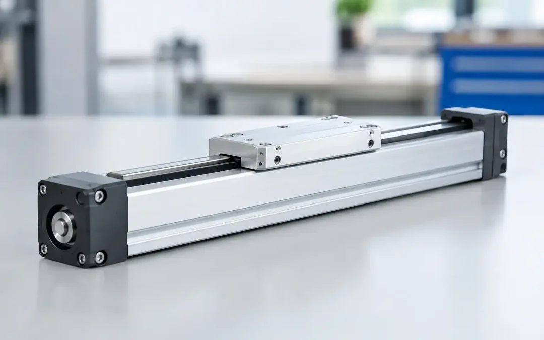
A conventional pneumatic cylinder can consume more machine length than the stroke it produces. That becomes a serious layout problem on transfer lines, guarded workcells, packaging equipment, and automated assembly stations. So, what is a rodless cylinder? It is a pneumatic actuator that moves a carriage along the outside of a cylinder body instead of extending a piston rod from one end.
The design allows a long stroke within a compact overall envelope. Rather than requiring room for a retracted cylinder plus an extended rod, the rodless cylinder keeps its motion inside the length of its profile. For OEMs and maintenance teams, that difference can reduce machine footprint, simplify guarding, and create more usable space for sensors, tooling, and cable management.
What Is a Rodless Cylinder?
A rodless cylinder uses compressed air to drive an internal piston, just as a standard double-acting cylinder does. The difference is how the piston transfers force to the external load. An external carriage is mechanically or magnetically coupled to the piston, allowing the carriage to travel along the cylinder body while carrying a fixture, gripper, tooling plate, or workpiece.
In a mechanically coupled design, a longitudinal slot runs through the cylinder tube. The piston connects directly to the carriage through that slot, while internal and external sealing bands close behind the moving connection. This creates a positive mechanical drive and is well suited to applications with higher loads, longer strokes, and demanding duty cycles.
In a magnetically coupled rodless cylinder, magnets inside the piston couple with magnets in an external carriage. The cylinder tube remains sealed, which is valuable where leakage control, cleanliness, or corrosion resistance is a priority. The trade-off is that the carriage can decouple if external resistance exceeds the magnetic coupling force. That makes load calculation and shock control especially important.
Why Engineers Use Rodless Cylinders
The main advantage is stroke efficiency. A conventional rod-style cylinder generally needs approximately twice its stroke length in installed space when fully extended. A 40-inch stroke, for example, can demand close to 80 inches of machine clearance depending on mounting and end attachments. A rodless cylinder with the same stroke typically needs only slightly more than the stroke length itself.
That compact geometry is only part of the value. The carriage on a rodless actuator is supported along the body, often with integrated guide bearings. This can allow the actuator to carry moment loads that would quickly damage a conventional cylinder rod or bushing. It is a practical choice for moving conveyor stops, pick-and-place tooling, inspection stations, doors, light robotic end effectors, and assemblies that cannot tolerate rod deflection.
A rodless cylinder can also reduce the number of components in a motion axis. In some cases, one guided rodless actuator replaces a standard cylinder, external linear rails, brackets, and a separate drive interface. Fewer interfaces can mean less alignment work during assembly and fewer parts to inspect when troubleshooting.
Still, a rodless cylinder is not automatically the best answer for every long-stroke pneumatic motion task. A standard cylinder may be lower cost for short strokes and purely axial loads. An electric actuator may be a better fit when position control, multi-position indexing, or controlled velocity throughout the stroke is required. The correct choice depends on force, payload, accuracy, speed, environment, and available air quality.
Mechanical and Magnetic Rodless Cylinder Designs
Mechanically Coupled Cylinders
Mechanically coupled rodless cylinders are generally selected when the application demands direct load transfer and higher resistance to side loads. Their external carriages can be fitted with plain bearings, recirculating ball guides, or roller guides depending on the load and accuracy requirement.
These cylinders are common on packaging equipment, panel handling systems, pallet transfer equipment, and long-travel automation axes. They offer dependable force transmission because the carriage is physically connected to the piston. However, the sealing system deserves attention. Contamination, damaged seal bands, improper mounting alignment, and inadequate lubrication can shorten service life.
Magnetically Coupled Cylinders
Magnetically coupled rodless cylinders are enclosed designs without a longitudinal body slot. That can make them useful in washdown-adjacent equipment, clean manufacturing areas, and applications where a smooth external profile is helpful.
Their limitation is coupling capacity. If a carriage hits a hard stop, accelerates too quickly, or encounters excess friction, the magnetic carriage may lose synchronization with the internal piston. The cylinder may still cycle internally while the load remains stationary. Proper end-of-stroke cushioning, conservative acceleration, and confirmed load margins are essential.
Sizing a Rodless Cylinder for Real Machine Conditions
Cylinder bore selection starts with available air pressure and required force. The basic relationship is force equals pressure multiplied by piston area, but the field calculation should include friction, guide resistance, fitting restrictions, and a reasonable design margin. A cylinder that only works at maximum plant pressure is not properly sized for production.
For horizontal moves, engineers often focus first on carriage mass and friction. For vertical moves, gravity becomes a constant opposing force, and load holding becomes a safety issue. A pneumatic rodless cylinder can move a vertical load, but it should not be the only means of preventing a suspended load from falling during air loss. Mechanical locks, counterbalance methods, or safety-rated design measures may be required.
Before specifying an actuator, confirm these five operating conditions:
- Total moving mass, including tooling, brackets, cable carriers, and product
- Stroke length, cycle rate, acceleration, and required travel time
- Center of gravity and the resulting pitch, yaw, and roll moments
- Available pressure, air cleanliness, lubrication requirements, and flow capacity
- Environment, including dust, washdown exposure, temperature, and chemical contact
Moment loading is often the missed variable. A carriage may have adequate thrust to move a load, yet still fail prematurely because the tool hangs too far from the guide centerline. Offset loads create leverage that acts on bearings and carriage surfaces. If the tooling must extend beyond the carriage, use the manufacturer’s published moment ratings and evaluate the worst-case position during acceleration and deceleration.
Installation Details That Protect Service Life
Rodless cylinders must be mounted on a flat, rigid structure. A twisted or bowed mounting surface can force the actuator body out of alignment and create carriage binding. Long-stroke units deserve particular care because small frame errors become more significant over distance.
Avoid using the cylinder itself as the structural member that corrects a poor machine frame. Align mounting surfaces first, tighten fasteners in the recommended sequence, and cycle the carriage by hand where practical before applying full operating pressure. If a cylinder runs freely at low speed but binds at production speed, inspect mounting flatness, external guide alignment, and cable carrier drag before assuming the actuator is defective.
End-of-stroke impact is another common source of damage. Pneumatic cushioning reduces impact energy but cannot compensate for excessive payload, high velocity, or uncontrolled exhaust flow. Properly sized flow controls should regulate speed, typically with meter-out control for stable pneumatic motion. External shock absorbers may be necessary for high-energy moves or applications with strict repeatability requirements.
Sensors should also be selected as part of the actuator package, not as an afterthought. Magnetic piston sensing can provide reliable end-position confirmation, but sensor brackets must remain secure and protected from collision. For critical operations, use sensor feedback to verify position before releasing a part, initiating a press cycle, or allowing the next machine station to operate.
Troubleshooting Common Rodless Cylinder Problems
A carriage that moves unevenly is often caused by binding rather than insufficient air pressure. Check for bent mounting surfaces, overhung loads, misaligned external rails, worn guide elements, or a cable carrier pulling sideways on the carriage. Increasing pressure may temporarily hide the issue while increasing wear.
Slow travel can result from undersized valves, restrictive tubing, clogged silencers, or poor flow-control adjustment. Long pneumatic lines create volume and response delay, especially on larger-bore cylinders. Mounting the directional valve closer to the actuator can improve response and reduce cycle inconsistency.
Air leakage on a mechanically coupled unit requires prompt inspection. Damaged seal bands or contamination in the slot area can reduce force and allow debris into the cylinder. For equipment operating in dusty or abrasive environments, consider protective covers, regular cleaning intervals, and a component design appropriate for the exposure.
When magnetic coupling is lost, do not simply reset the carriage and restart production. Identify why the load exceeded coupling capacity. A collision, excessive acceleration, increased friction, or an added fixture may have changed the system load beyond the original design condition.
Choosing an Actuator That Matches the Application
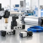
A rodless cylinder should be specified as a motion system, not merely by bore and stroke. The actuator, guide type, mounting arrangement, valve package, air preparation, sensors, and external load all affect uptime. That is why configured-to-order support is valuable when an application includes long travel, offset tooling, high cycle counts, or uncertain environmental conditions.
For demanding automation equipment, VidoAir can help align bore size, stroke, guide configuration, and pneumatic control components with the actual operating conditions. The objective is not just to move a load on a test bench. It is to maintain controlled, repeatable motion through production shifts.
The best rodless cylinder installation is usually the one that receives the most attention before it reaches the machine. Measure the load, account for moments and impact energy, protect the actuator from contamination, and leave access for adjustment and inspection. Those decisions turn a space-saving actuator into a dependable production axis.