A gripper that holds a part securely at the bench can still fail on the machine. High acceleration, oily surfaces, off-center loads, pressure drop, and poorly designed fingers all reduce real-world holding performance. Knowing how to choose pneumatic grippers means sizing the complete handling system, not simply selecting the unit with the highest catalog force.
For OEMs, integrators, and maintenance teams, the right choice protects cycle time, product quality, and uptime. The wrong one creates intermittent drops, damaged workpieces, jaw misalignment, and difficult troubleshooting after the cell is already commissioned.
Start With the Actual Part and Handling Sequence
Begin with the workpiece, not the gripper catalog. Record its weight, dimensions, material, surface condition, temperature, and allowable contact area. A smooth steel stamping, a porous casting, a plastic injection-molded housing, and a thin-walled aluminum tube may require entirely different gripping approaches even when they weigh the same.
Next, map the motion sequence. Determine whether the gripper picks from a fixed nest, a moving conveyor, a pallet, or another robot. Identify lift direction, acceleration, deceleration, rotation, and any transfer through a washdown, welding, or machining zone. A part handled vertically during a slow pick-and-place cycle needs less grip force than the same part moved sideways at high speed by a robot arm.
Part geometry also determines where the gripping force can be applied. External gripping is common when jaws can close on outside surfaces or a defined flange. Internal gripping may be better for rings, tubes, and components whose exterior must remain free of marks. If a part has no repeatable surface for rigid jaws, consider compliant fingers, contoured tooling, or a soft robotic gripper rather than forcing a standard parallel gripper into the application.
Choose the Pneumatic Gripper Style Before Sizing Force
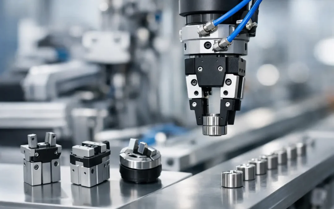
The basic gripper mechanism affects access, repeatability, jaw travel, and usable force. Parallel grippers are the default choice for many automation cells because both jaws move symmetrically. They work well for centering parts, pallet loading, assembly, and machine tending.
Angular grippers provide wide jaw opening in a compact envelope. They are useful where fingers must clear a fixture, mold, or conveyor during loading. Their trade-off is that jaw paths are arcing rather than linear, which can complicate finger design and reduce control over part centering.
Three-jaw grippers are well suited to round or irregular components that benefit from self-centering contact. Long-stroke grippers serve applications with significant variation in part size or access distance, but longer travel can increase cycle time and reduce available force. For delicate, deformable, or uneven products, soft robotic grippers can distribute force across a larger area and reduce damage risk.
Do not select a style solely because it resembles an existing unit. A legacy gripper may have been chosen around a previous fixture, lower production rate, or different part finish. Reusing it without reviewing the present duty cycle can carry old reliability problems into a new line.
Calculate Grip Force for Real Operating Conditions
Catalog grip force is only a starting point. Manufacturers commonly state force per jaw or total gripping force, at a specified air pressure and jaw position. Confirm which value is published before comparing products. Also check the force curve: many pneumatic grippers deliver different force levels across their stroke.
For friction gripping, the required force depends on the load, coefficient of friction, direction of motion, acceleration, and safety factor. A simplified approach is to calculate the external force trying to move the workpiece, then divide it by the available friction coefficient and the number of gripping contacts. Add an appropriate safety margin for surface variation, pressure loss, vibration, and wear.
For example, a dry machined aluminum part may appear easy to grip, but coolant residue can sharply lower friction. A gripper sized around dry conditions may occasionally slip after a machine cycle or cleaning process. In that case, more force may help, but a better answer may be a shaped finger, a mechanical stop, or a positive feature that resists the load without depending entirely on friction.
Avoid excessive force as well. Over-gripping can distort thin-wall parts, crack molded components, damage cosmetic finishes, and shorten jaw-guide life. The strongest gripper is not automatically the most reliable selection. The target is stable retention with the lowest practical force and a finger design that supports the load predictably.
Account for Moment Loads and Finger Design
Long custom fingers can turn a correctly sized gripper into an overloaded assembly. Every millimeter between the jaw guide and the point of contact increases the moment applied to the jaws. A heavy part held far from the gripper centerline creates additional bending load during acceleration and can cause jaw play, uneven wear, or loss of repeatability.
Review the gripper’s permissible moment ratings for all relevant axes, not just the maximum gripping force. These ratings should include the finger weight, workpiece center of gravity, and dynamic loading. If the application needs extended fingers, consider a larger gripper body, a guided slide solution, or supporting the part with an auxiliary locator during transfer.
Finger material and contact geometry matter just as much. Hardened steel may be appropriate for hot or abrasive parts, while aluminum or engineered polymer fingers can reduce part marking and moving mass. Add replaceable pads where wear is expected. For high-volume applications, design fingers so a technician can replace wear surfaces without removing the complete gripper from the machine.
Match Air Pressure, Air Quality, and Speed
A pneumatic gripper cannot deliver rated performance without stable air supply. Verify the available pressure at the gripper during peak machine demand, not only at the compressor or main header. Undersized tubing, restrictive fittings, long runs, and multiple devices cycling at once can create pressure drop at the exact moment the gripper needs to close.
Air preparation should match the environment and the gripper manufacturer’s lubrication requirements. Clean, dry, regulated air supports consistent operation and longer seal life. In wet, corrosive, food-adjacent, or washdown environments, use appropriate materials, sealing, and stainless steel air preparation equipment where the operating conditions demand it.
Gripper speed is also a tuning decision. Fast jaw motion can reduce cycle time, but it may cause impact damage, bounce, or part displacement. Flow controls mounted close to the actuator allow better adjustment than controls placed far upstream. Where cycle consistency is critical, test the gripper at production pressure, with production tooling and the expected line speed.
Specify Mounting, Sensors, and Maintenance Access
A gripper must fit the machine mechanically and electrically as well as pneumatically. Confirm mounting face, bolt pattern, clearance through the full jaw stroke, tubing routing, and access for finger changes. On robot end effectors, minimize mass and keep the center of gravity close to the wrist to protect payload capacity and motion performance.
Position sensing is often worth specifying even when the process seems simple. Magnetic sensors can confirm open and closed jaw positions, helping the PLC identify a failed stroke before a robot moves a partially gripped part. For tight-tolerance assembly, a closed sensor alone may not prove that the correct part is present. Add part-present sensing or process verification when an empty grip could create a costly downstream error.
Consider what maintenance will look like after six months of production. Can technicians inspect fittings, replace sensors, and service fingers without dismantling guarding or removing the end effector? Components selected for easy access reduce mean time to repair and make preventive maintenance more practical.
Validate the Selection Under Worst-Case Conditions
Before releasing a design, run a practical validation using the most demanding credible condition: minimum plant pressure, maximum part weight, highest acceleration, worn contact pads, and the lowest expected friction. Test startup behavior after downtime, not only steady-state cycling. Check that the part remains stable during emergency stops, robot orientation changes, and conveyor interruptions.
Document the selected pressure, flow-control setting, finger material, sensor logic, and replacement wear items. This turns a one-time design choice into a repeatable standard for future cells and replacement orders. For applications involving unusual geometry, aggressive environments, or high-speed motion, factory-direct technical support can help confirm gripper configuration before production hardware is committed.
The best time to find a marginal gripping condition is while the part is still in a test fixture. Build that margin into the gripper, fingers, air circuit, and control logic before the first production shift has to discover it for you.