A manifold that fits the valve catalog but not the machine can create expensive problems: slow cylinder motion, confusing I/O faults, inaccessible replacement valves, and air leaks hidden inside a crowded panel. Knowing how to choose solenoid manifolds starts with the circuit and application, not with valve size alone. The right assembly should reduce tubing, simplify commissioning, and give maintenance technicians a clear path to diagnose and replace a failed station without disrupting the rest of the machine.
Start With the Machine Function, Not the Manifold
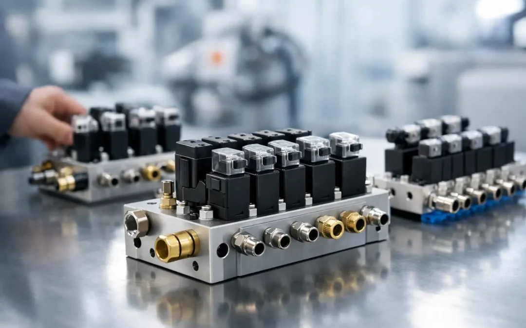
A solenoid manifold is a valve platform that distributes supply air and exhaust while allowing multiple directional control valves to share a common base, electrical connection system, or both. That shared architecture is its advantage, but it also means one decision can affect every actuator connected to the bank.
Begin by mapping each pneumatic function. Identify whether each actuator needs a 2-position single-solenoid valve, a 2-position double-solenoid valve, or a 3-position valve with center exhaust, center pressure, or closed center. These configurations behave very differently during a power loss, emergency stop, or cycle interruption.
For example, a single-solenoid spring-return valve moves to its normal state when power is removed. This can be the preferred choice for a clamp that must retract or a reject mechanism that must return to a safe position. A double-solenoid valve holds its last shifted state after the signal is removed, which can be useful where maintaining position matters but may be unsuitable for a safety-related function. A 3-position center condition should be selected based on what the cylinder must do between commands, not simply because it appears more flexible.
Also separate actuators by operating pressure where necessary. If one group of devices requires lower regulated pressure than another, placing all valves on one common-pressure manifold may force a compromise. Use separate regulated feeds, pressure zones, or separate manifold assemblies when the application requires different force levels or independent pressure control.
How to Choose Solenoid Manifolds by Flow Requirement
The manifold and valve must deliver enough flow to achieve the required cylinder speed at the available pressure. A cylinder may extend slowly even when the valve shifts correctly if the selected flow capacity, fittings, silencers, or tubing restrict the circuit.
Calculate the actuator air demand from bore size, stroke, cycle rate, and operating pressure. Then compare it with the valve’s rated flow coefficient or standardized flow rating. Do not treat this value as an isolated specification. Flow through a manifold station is affected by the supply port size, common internal galleries, exhaust capacity, and the number of valves operating simultaneously.
A compact valve family may be ideal for small grippers, stops, and sensor-triggered mechanisms. It may be undersized for a large-bore cylinder that must cycle quickly, especially if several cylinders move at the same time. In those cases, a larger valve platform, a manifold with higher-flow supply and exhaust ports, or locally mounted valves can improve response time.
Exhaust deserves equal attention. Restricted exhaust creates backpressure that slows cylinder return and can cause inconsistent motion. This frequently appears after a machine modification, when extra silencers, long exhaust plumbing, or high-cycle stations are added to a manifold originally sized for lighter duty. Check whether the manifold provides common exhaust, individual exhaust, or options for remote exhaust routing. For dirty environments, remote exhaust can keep contamination away from the work area, but it must be sized correctly.
Match Porting and Tubing to Serviceability
Port size should support the required flow without making installation unnecessarily bulky. Small push-to-connect ports reduce package size and work well for compact automation. Larger threaded ports or sub-base connections are better suited to higher-flow cylinders, long tubing runs, and heavy equipment.
Consider where the manifold will be mounted before specifying port orientation. Side ports, bottom ports, and top ports change how easily tubing can be routed and traced. A clean CAD layout can become difficult to service once fittings, bend radius, cable trays, and guarding are installed.
For maintenance-heavy equipment, label every station by function and preserve enough space to remove a valve or fitting. Avoid routing tubes across manual overrides, LED indicators, or retaining screws. A manifold that takes five minutes to troubleshoot is more valuable to plant operations than one that merely saves a few inches of panel space.
Specify Electrical Architecture Early
Electrical integration is often where an otherwise correct manifold becomes a commissioning delay. Confirm coil voltage first, including the actual control voltage available at the machine. Common options include 24 VDC, 12 VDC, 120 VAC, and 230 VAC. Most modern automation equipment uses 24 VDC, but replacement applications often require matching an existing voltage standard.
Then select the connection method. Individual lead wires or DIN-style connectors are straightforward for small valve banks and simple retrofit work. Multi-pin connectors reduce wiring labor on medium-size assemblies. Fieldbus valve manifolds can reduce cabinet wiring substantially by placing distributed I/O near the actuators, with network communication back to the controller.
The fieldbus option is not automatically the right answer. It adds address configuration, network diagnostics, and electronic module considerations. For a compact machine with four valves near the main panel, discrete wiring may be faster to build and easier for a technician to verify with a meter. For a large machine with many remote pneumatic functions, a networked manifold can reduce wire count, improve modularity, and make expansion cleaner.
Check current draw as well. The PLC output, relay, fuse, cable size, and power supply must accommodate the inrush and holding current of every energized coil. If multiple valves may energize at once, size the electrical system for that realistic peak condition rather than one coil at a time.
Evaluate Environment and Media Compatibility
Standard aluminum-bodied manifolds are effective for dry, filtered compressed air in protected machine environments. Demanding applications may require more consideration. Washdown areas, corrosive atmospheres, outdoor equipment, food processing, and refrigeration systems can call for higher ingress protection, corrosion-resistant hardware, stainless steel air preparation components, or specialized seals.
Ambient temperature matters because coil performance, seal flexibility, and condensation behavior all change at temperature extremes. Confirm the full operating range, not just the normal plant temperature. Also assess air quality. Water, compressor oil carryover, pipe scale, and debris can cause spool sticking, seal wear, and shortened valve life.
Proper air preparation protects the manifold investment. Filtration should match the valve manufacturer’s contamination tolerance, and lubrication should only be used where the valve design and downstream equipment permit it. Once lubricated air is introduced into many pneumatic systems, continued lubrication may be required to avoid drying seals.
Build in Isolation, Expansion, and Fault Recovery
The best manifold specification considers the next service event. Use an accessible shutoff and controlled exhaust arrangement so technicians can isolate the pneumatic circuit safely before replacing a valve. Where machine design permits, pressure zones can isolate a section of actuators without removing air from the entire system.
Plan spare stations if the OEM expects future options, additional sensors, or extra cylinders. Adding two unused positions during the original build is often less costly than replacing a fully populated manifold later. Verify that blanking plates, end plates, wiring capacity, and network node limits support the planned expansion.
Manual overrides are another practical decision. They are useful during commissioning and troubleshooting, but their style matters. Non-locking overrides reduce the chance of leaving a valve manually actuated. Locking overrides can help with setup tasks, but they require disciplined procedures to prevent unexpected movement.
For critical production machinery, consider how a failed station will be replaced. A plug-in valve design can minimize downtime, while a manifold requiring extensive tubing removal can turn a minor coil or spool failure into a longer repair. Keep a documented valve part number, coil voltage, circuit symbol, and station map in the machine file.
Validate the Complete Assembly Before Release
Before releasing a manifold for production, verify the circuit symbols against the actual actuator sequence, confirm the port naming convention, and check that pressure and exhaust connections match the pneumatic schematic. Review the assembly under simultaneous motion, low supply pressure, and power-loss conditions. These are the conditions that reveal undersized flow paths and incorrect fail positions.
VidoAir supports configured pneumatic solutions for applications where valve function, porting, electrical connection, and delivery schedule must align with the machine build. The strongest specification is one that gives production the cycle performance it needs while giving maintenance a layout it can understand at a glance.
A well-chosen solenoid manifold should disappear into normal operation. When it does require attention, clear labeling, accessible stations, correct electrical architecture, and a serviceable air circuit will let your team restore motion quickly and keep the machine earning its place on the floor.